Trail Object
The Trail object will generate splines from the path of the particles during the animation. The splines can then be used to generate other objects, such as in a Sweep object, or rendered with the X-Particles material.
Note: each emitter should only be associated with one Trail object. If you try to link two or more Trail objects to the same emitter, results are unpredictable and almost certainly not what you wanted.
If you try to use the same emitter with two Trail objects, it won't work; you may get splines but they may be distorted or missing parts. The reason is that each particle can only carry one set of data used by the Trail object, and if there are two Trail objects competing for the same data, it will become corrupted and the splines will not be generated correctly.
Interface
The interface contains the following sections:
For the 'Groups Affected' tab and for the buttons at the bottom of the interface, please see the 'Common interface elements' page.
Quick links to specific topics:
- Settings for the 'No Connection' algorithm
- Settings for Connection algorithms
- Caching trails
- A note on memory usage
Parameters
General quicktab
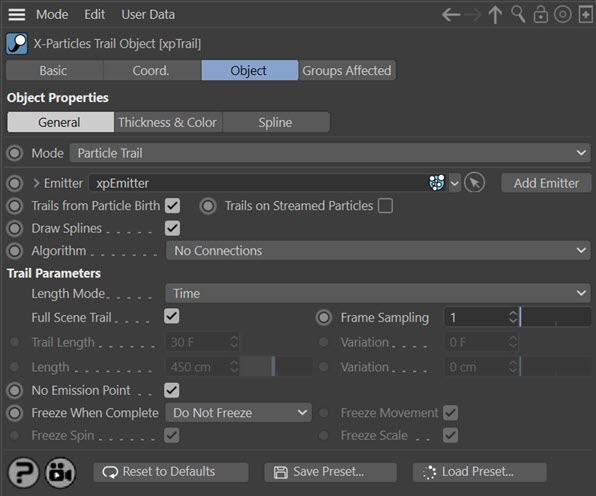
Mode
The Trail object has two modes. One is to create trails from an X-Particles emitter; the other is to create trails from a moving object. This menu has two options:
Particle Trail
Create particle trails (requires an X-Particles emitter). This is the default mode.
Object Trail
Creates trails from an object in the scene. Does not require an emitter. For details of this mode, see the 'Object Trails' section below.
Particle Trails
Emitter
For objects to be generated from particles, you must tell the Trail object which emitter it will work with. Drag an emitter object into this field to do that.
Add Emitter
Click this button to create a new emitter and add it to the 'Emitter' link field.
Trails From Particle Birth
If this switch is checked, a trail will be generated for each particle as soon as it is created. If it is unchecked, no trail will be generated for newly-created particles until this switch is checked again, or until trail generation for a particle is turned on by an Action.
You should normally leave this switch checked unless you are sure you want to turn it off.
Trails on Streamed Particles
This is a special switch for use with the Tendril modifier. That modifier generates a lot of additional particles, and usually you would not want them to have their own trails. If this switch is unchecked, no trails will be generated for particles created by the Tendril modifier. If checked, each particle generated by the Tendril modifier will have its own individual trail.
It is recommended that you normally leave this switch unchecked.
Draw Splines
If unchecked, the Trail object will not generate splines, so they will not appear in the editor or be rendered, and cannot be used in a Spline Mesher object or in a Sweep object.
Algorithm
This drop-down list has several settings to determine how trails can be used to connect particles or points in the generated trail:
- No connections
- Straight Sequence
- Segmented Sequence
- Multiple Sequence
- All Points to all Points
- Nearest by Index
- Nearest by Distance
- Cluster
- Tendrils
- Constraints
- Infectio
Settings for 'No Connections' algorithm
These are the basic particle trails. Each particle has its own trail which can be rendered, used in the Spline Mesher or a Sweep object, etc.
Length Mode
The Trail length can be calculated in one of two ways: the time taken to draw the trail or the actual length in scene units. This drop-down lets you select the required option.
Full Scene Trail
If checked, this will cause the Trail object to generate trails which are as long as the scene length. If unchecked, the trail length can be set with the 'Trail Length' and 'Variation' settings. Only used if 'Length Mode' is set to 'Time'.
Frame Sampling
By default, the spline will contain one point for each frame of the particle's life. You can reduce the number of samples by increasing the value here.
The Frame sampling does not change the length of the spline. It alters the distance between points in the generated spline. You might want to do this for smoother splines when generating wavy splines - e.g. if the particles are being influenced by a Turbulence modifier. If you are generating splines which are only generated for less than the number of frames in the scene, it is recommended you leave this set at one. Otherwise you will see a slightly jerky movement of the spline as it follows the particle due to the reduced number of samples.
Only used if 'Length Mode' is set to 'Time'.
Trail Length
The length of the trail which will be produced, in frames. A setting of 30, for example, will generate a trail over 30 frames of the particle's life, and will then cease to grow (but will not be removed, and will continue to follow the particle). If you want trails to be generated for the entire life of every particle, turn on the 'Full Scene Trail' switch instead of using this setting.
Only used if 'Length Mode' is set to 'Time'.
Variation
This setting can be used to generate random variation in trail length. The value in this field is combined with the 'Trail Length' setting to produce trails of different lengths on each particle.
Only used if 'Length Mode' is set to 'Time'.
Length, Variation
The maximum length of the trail in scene units. Only used if 'Length Mode' is set to 'Length'.
No Emission Point
n previous versions of X-Particles, the first point of the trail was created after the emitter had created the particle and moved it along the distance governed by its speed. This invariably left a small gap between the point of origin of the particle and the beginning of the trail spline. Most of the time this didn't matter, but if the particle was emitted from an object and you wanted the trail to have no gap between it and the source object, there was no easy way to do this.
In the latest version of X-Particles, an extra point in the trail spline can be generated at the point of origin of the particle. Because this can cause problems with scenes created in previous versions, this feature is disabled by default. To enable it, uncheck this switch.
Freeze When Complete
This drop-down is used to control what happens when the trail reaches its maximum length. It has three options:
Do Not Freeze
This is the default setting. When a trail reaches its maximum length the particle keeps moving, dragging its trail behind it.
Freeze Particle
If you want the particle to stop once the trail reaches the maximum length, check this switch. You can further opt to halt particle movement, spin, and scale independently.
Note: this is a global setting. If it is turned on, it will apply to all particles. If you want to freeze individual particles when their trail is complete without affecting other particles, use the Freeze Action.
Freeze Trail
With this option, the particle will not be frozen but the trail will be, so the trail and the particle will be disconnected.
Freeze Movement/Spin/Scale
You can use these switches to affect particle movement, spin, and scale independently. Note that if none of these switches are checked, nothing will happen even if 'Freeze When Complete' is set to 'Freeze Particle'.
Settings for Connection algorithms
A variety of different algorithms are available for connecting particles together.
The available algorithms are:
- Straight Sequence
- Segmented Sequence
- Multiple Sequence
- All Points to all Points
- Nearest by Index
- Nearest by Distance
- Cluster
- Tendrils
- Constraints
- Infectio
Straight Sequence
Each particle is connected to the next one in the particle stream to form a single trail. There is one parameter:
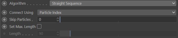
Connect Using
In previous versions of X-Particles the connection in this mode was always between particles next to one another in the particle array. However, if some particles in the middle of the array were killed, the remaining particles were moved to fill the gap. This caused their index value to change and so the connected spline would change - sometimes drastically.
This menu has two options:
Particle Index
This is the method used in previous versions, and is the default method to avoid causing problems with scenes created in those versions.
Particle Unique ID
If you choose this option, the particles are connected using their own unique ID values. These IDs are assigned in sequence, but never change, so if a particle in the middle of the particle array is deleted, the previous particle will simply connect to the particle with the next ID, minimising any change to the trail spline. It is recommended that you use this setting for all new scenes created in X-Particles.
Skip Particles
This enables you to skip over the specified number of particles when connecting them together. For example, if the value in this setting was 2, particle 1 would be connected to particle 4 (skipping 2 and 3), particle 4 to particle 7 (skipping 5 and 6) and so on.
Set Max. Length
The maximum length of the single trail can be set if this switch is checked. If checked, the maximum length is set in the 'Length' parameter.
Length
The maximum length of the spline if 'Set Max. Length' is checked.
Segmented Sequence
This is similar to 'Straight Sequence' but enables you to divide the spline up into short segments with gaps between them. There are two parameters:
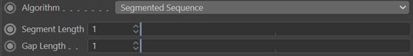
Segment Length
The length of each segment. The default value of 1 is the shortest possible segment, consisting of two adjacent particles linked together.
Gap Length
The length of the gap between segments. The default value of 1 is the shortest possible gap, which is the gap between two adjacent particles.
Multiple Sequence
This is similar to 'Straight Sequence' but instead of a single long spline, you can emit multiple splines of varying length.
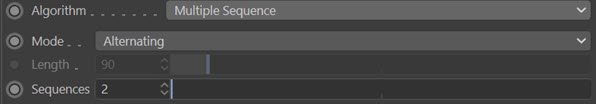
Mode
There are two ways to generate the splines from the particles. These are:
Alternating
Each spline will be generated by taking a particle for each spline in turn then adding further points, again taking particles in turn. For example, if 'Sequences' is set to 2, splines will be created by joining particle 1 to particle 3, then to particle 5 and so on; then another spline will be created by joining particle 2 to particle 4, to particle 6, etc.
Sequential
With this mode, the number of splines is controlled by the 'Length' parameter, which is the number of points in each spline. For example, if this is set to 10, a spline will be created using particles 1 to 10, then another spline using particles 11 to 20, etc.
Length
The length of the spline in terms of the number of particles used to create it. Only used in 'Sequential' mode.
Sequences
The number of sequences created by selecting particles in turn. Only used in 'Alternating' mode.
All Points to all Points
In this mode, each particle is connected to every other particle to form a complex net. There are no other parameters.
Nearest by Index, Nearest by Distance, and Cluster
These algorithms share some common elements, the most important being the ability to specify which particle groups are used.
Destination Group
When you select Nearest by Index, Nearest by Distance, or Cluster the options change, depending on the connection type. Common to all three however is this drop-down menu and link field:

This lets you select which particle groups are used in making the connections. The available options are:
- Use All Groups: each particle will form connections to other particles regardless of which group they are in
- Only Same Group: each particle will only form connections to particles in the same group as itself
- Only Different Groups: each particle will only form connections to particles in different groups to itself
- Specific Group: each particle will only form connections to particles in a specific group; specify which group to use by dragging the Group object into the 'Group' link field
- All Except Specific Group: each particle will only form connections to particles which are NOT in a specific group; specify which group to use by dragging the Group object into the 'Group' link field
Group
The group to use in either of the two specific group options.
Nearest by Index
This mode displays the following settings:
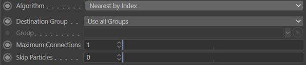
Each particle is connected to the nearest other particle(s) where proximity is measured, not by distance, but by the index in the particle stream. The options 'Maximum Connections' and 'Skip Particles' are available with this setting.
Maximum Connections
For example, with the default settings, particle 1 would connect with particle 2, 2 to 3, 3 to 4, and so on. This is, of course, identical to 'Straight Sequence' mode. If 'Maximum Connections' is set to 2, then particle 1 will connect to particles 2 and 3, 2 to 3 and 4, etc. If 'Skip Particles' is set to higher than zero, not all particles will make connections. So in the previous example, if 'Skip Particles' is set to 1, particle 1 will connect to 2 and 3, particle 2 will be skipped and will not connect to any particles, particle 3 will connect to 4 and 5, particle 4 will be skipped, etc.
Skip Particles
This works as described above in 'Maximum Connections'.
Note: 'Maximum Connections' must be set to at least 2 for 'Skip Particles' to work. This is because at least two connections are required for particle skipping to function.
Nearest by Distance
This mode displays the following settings:
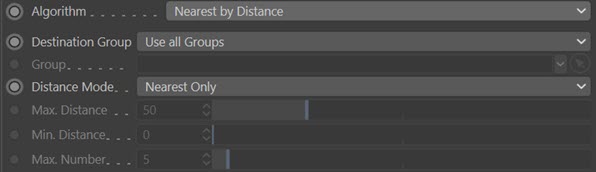
In this mode particles are connected to each other depending on the distance between them in the 3D world. The Distance mode drop-down becomes available, with these options:
Distance Mode
- Nearest Only: each particle will connect to its physically closest neighbour
- All Within Distance: each particle will connect to every other particle which is closer to it than the value given in the 'Max. Distance' setting and no closer than the 'Min. Distance' setting. Increasing the 'Max. Distance' value or decreasing the 'Min. Distance' value will result in more connections because more particles will be within that distance range.
- Max. Number Within Distance: this is the same as 'All Within Distance' except that you can use the 'Max. Number' setting to limit the maximum number of connections. For example, if this is set to 5, and there are 10 particles within the threshold distance, connections will only be made to the 5 closest particles.
Max. Distance, Min. Distance
If particles are closer together than 'Min Distance', or farther apart than 'Max. Distance', they will not form a connection.
Max. Number
This is the maximum number of connections a particle can make.
Note that in 'Nearest by Distance' mode, the generated spline may change radically over time as the distance between individual particles changes.
Cluster
This mode displays the following settings:
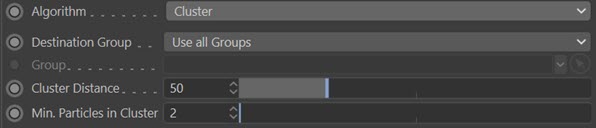
In this mode particles are connected to each other in groups or clusters. There are two settings:
Cluster Distance
All particles in a cluster must be within this distance of one another. Increasing this value will give larger clusters but fewer of them,
Min. Particles in Cluster
The absolute minimum is 2, in which case the two particles are linked by a straight line. As this value is increased, there must at least this many particles within the 'Cluster Distance' of one another to form a cluster.
Tendrils
This is a special mode for use with the Tendril modifier. It causes the Trail object to generate a single trail connecting all the particles in each tendril. There are no other parameters.
Constraints
If you are using constraints (see the Constraints object), collisions (see the Collider tag) or particle to particle collisions (see the Particle-Particle Collisions object) you can use this option to create a spline for each constraint or collision. The spline can then be rendered with an XP Material (or the Hair renderer) or used in a Spline Mesher object (or Sweep object).
To create trails for these constraints you must first turn on the required constraints in the Constraints object, then choose the constraints which will become splines in this section, like so:
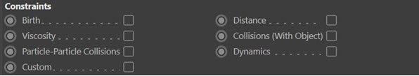
Simply check the constraints to be included by the Trail object.
Collisions (With Object)
To enable trails in this case requires a little more work. You should:
- add a Collider tag to the relevant object
- in the tag's 'Connect' section, turn on 'Connect on Collision'
- in the Trail object, turn on 'Collisions (With Object)'
When a particle collides with the object it will connect to it and you will see effects like this:
Particle-Particle Collisions
To generate trails when a particle to particle collision occurs, do this:
- add a Particle-Particle Collision object to the scene
- in that object, turn on the switch 'Connect on Collision'
- in the Trail object, turn on 'Particle-Particle Collisions'
Then a trail will be generated between particles when a collision occurs between them.
Infectio
This is a special mode for use with the Infectio modifier. It has the following settings:
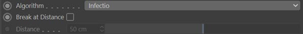
Break at Distance
If this switch is checked, trails will not be drawn between particles when the distance between them exceeds the value in the 'Distance' setting.
Distance
The maximum distance between two particles for a trail to be drawn. Only available if 'Break at Distance' is checked.
Thickness & Color quicktab
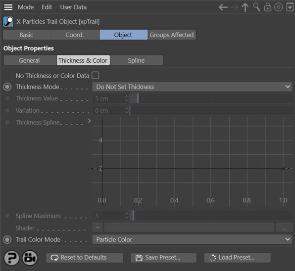
These settings generate additional data to control the 'thickness' of a trail. This data is used by the X-Particles material to alter the 'thickness' and/or colour of the rendered spline.
Note: these options are not available in 'Object Trail' mode.
Thickness Mode
This drop-down controls how thickness is generated. It has six settings (note: not all options are available with all connection algorithms):
Do Not Set Thickness
No thickness data is created.
Set From Value
With this option, the 'Thickness Value' and 'Variation' parameters become available and will set a uniform thickness along each trail.
Use Spline
If this option is selected the 'Thickness Spline' and 'Spline Maximum' parameters become available. You can then set the thickness along the length of the trail with the spline control.
Note: this option is not available if the connection algorithm is set to 'Cluster' or 'Constraints'.
Use Shader
If this option is selected the 'Shader' link field becomes available. If you add a shader to this link, the shader is sampled for all points along the trail and that value is then multiplied with the value in 'Thickness Value' to give the thickness along the length of each trail.
Use Radius (Current)
This is the same as the 'Use Radius' option from previous versions. With this option the thickness depends on the current particle radius. No other settings are then available. By 'current particle radius' we mean the radius the particle has at any given frame. This means that the thickness of the trail will be the same at all points and changing the particle radius (e.g. with a Scale modifier) will alter the thickness of the whole trail.
Note: this option is only available if the connection algorithm is set to 'No Connections' or 'Tendrils'.
Use Radius (Variable)
>This is the same as 'Use Radius (Current)' but instead of just using the particle's current radius the radius is stored for each point in the trail. This means that changing the particle radius will result in variable thickness along the spline.
Note: this option is only available if the connection algorithm is set to 'No Connections''.
Thickness Value and Variation
These fields are used to set the thickness in 'Set From Value' mode and (for 'Thickness Value' only) in the 'Use Shader' mode.
Thickness Spline
The spline control is used to set the thickness in 'Use Spline' mode. The thickness at the start of the trail is obtained from the value at the extreme left of the spline; the thickness at the end from the extreme right of the spline.
Spline Maximum
This is the maximum possible value in the spline (by default, it is set to 100). You can change the maximum value with this setting.
Shader
Use this link field to choose a shader when in 'Use Shader' mode. A noise shader works well in this field, and can be animated to give thickness which varies with time.
Color Mode
In addition to thickness, the trail color can now be set for individual particle trails. This drop-down menu controls how the colour is used. The options are:
Particle Color
The entire trail has the same colour, derived from the particle's colour. If you change the particle's colour, its trail changes to that colour along its length.
Per-Vertex Color
A colour is stored for each vertex in the trail spline. If you change the particle colour, that colour is used for all new spline vertices but existing ones are unchanged. This enables you to have multicoloured trails for each particle.
Constraint Color
If the 'Algorithm' menu is set to 'Constraints' the 'Per-Vertex' option is removed and instead the option is 'Constraint Color'. Selecting this option will use the colour given for the constraints in the emitter's Display tab. See the 'Display Constraints' setting in the emitter for more details.
Spline quicktab
Please note: if you load a file created with XP3.5 into later versions of X-Particles, and in the original file you changed any of these settings, the settings are not preserved when loading the file. You will need to reset them manually if you still need them to be changed from the default values.
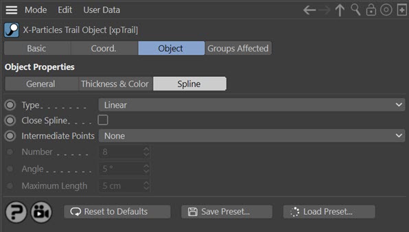
The settings in this section are exactly the same as all other splines in Cinema 4D. Please refer to the C4D documentation for details.
Note that the spline type is only available when 'Algorithm' is set to 'No Connections', 'Straight Sequence' or 'Cluster'. In other modes the spline will always appear to be linear (since the trail is then made up from multiple, independent, very short splines which cannot show curves).
Important: do not subdivide the spline (i.e. you should leave intermediate points as 'None') if you want to use the spline renderer to render the trail. Using intermediate points will cause the spline renderer to ignore the thickness setting and the colour. This is currently a limitation of the system.
Caching trails
The Cache object can cache trails in the same way as other X-Particles generator objects. Once a trail has been cached, you no longer need the emitter originally used to create the trails, so you can delete it from the scene if you like, or turn it off - the particles are no longer needed for the trail.
There is an exception to this, however. To use the particle colour on a cached trail when rendered you must have an emitter linked to the trail object. This can be the emitter used to create the trail in the first place, which in turn can either be cached or uncached, or it can even be a completely different emitter as long as it emits at least one particle per spline in the trail object. Without an emitter the trails will only use the single colour when rendered.
In the vast majority of cases you will probably cache both the emitter used to create the trails and the trail object, in which case you don't need to add or change anything and the trails will be rendered with their original colour.
Note that 'Object Trail' mode cannot be cached at this time.
A note on memory usage
When a trail is created, X-Particles must allocate sufficient memory to store the particle positions, and the actual trail spline is constructed using those stored position values. This can use up a lot of RAM very quickly. For example, if you have a scene which is 5000 frames long and 'Full Scene Trail' is checked each trail will use almost 100K of memory by the end of the scene. With high particle birthrates, this can use up available RAM and risk out-of-memory errors.
To reduce memory use, especially with long scenes and high particle counts, consider whether you really need the trails to be the full length of the scene. If you don't, you can reduce the memory requirement significantly by unchecking 'Full Scene Trail' and setting the 'Trail Length' to the required value.
Object Trails
When you select this option in 'Mode' the interface changes to this:
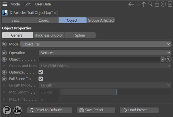
With this option, you can create trails from an object rather than particles. The parameters are as follows.
Operation
This menu controls where the trails will commence from. The options are:
Vertices
Trails are created from the object's vertices.
Polygon Centres
Trails are created from the centre of each polygon in the object (assuming it has polygons, of course).
Object Axis
A single trail is created from the object's axis.
Object
Drag the object you want to use into this link field. Note that if you want to use the vertices or polygon centres as the source of trails, the object must have one or more vertices or polygons (or be an object which, if it was made editable, would do so).
Cloners and Nulls
This menu controls what happens if you add a Mograph Cloner or a Null object to the link field. It is only available if 'Operation' is set to 'Object Axis'. The choices are:
Use Child Objects
In this case each child object of a null object, or the clones produced by a cloner, are used as the source for the trails. The null or cloner object itself does not generate a trail.
Use as a Single Object
With this option the clones or child objects are ignored and a single trail is generated from the position of the cloner or null object itself.
If you want to create a single trail from a Null object, be sure to set 'Operation' to 'Object Axis' then set 'Cloners and Nulls' to 'Use as a Single Object'. No other combination will work with a null object with no child objects.
Optimize
Not available if 'Operation' is set to 'Object Axis'.
In the other modes, the Trail object will automatically collapse any object in the link field to produce or more editable objects, then will join them all together to produce a single editable object. This can sometimes lead to duplicated points and polygons. If this switch is checked, the collapsed mesh will be optimized before being used to generate trails. Most of the time this should remain checked but you can skip that step if you need to by unchecking this switch.
Full Scene Trail
If this is checked, the trail length will be that of the scene. If it is unchecked, there are additional options to set the desired length.
Length Mode
Only available if 'Full Scene Trail' is unchecked. Select from this menu how the length should be managed.
Length
Select this option to set a maximum length in scene units of the trail. The length is specified in the 'Max. Length' parameter.
Time
Select this option to set a maximum time for the trail generation. One point per trail is added for each frame, so if this option is selected and 'Max. Time' is set to 30 frames, the trail will be 31 points long (the extra point is produced on the starting frame of the scene).
Max. Length
The maximum length of the trail if 'Length Mode' is set to 'Length'.
Max. Time
The maximum length of the trail if 'Length Mode' is set to 'Time'.