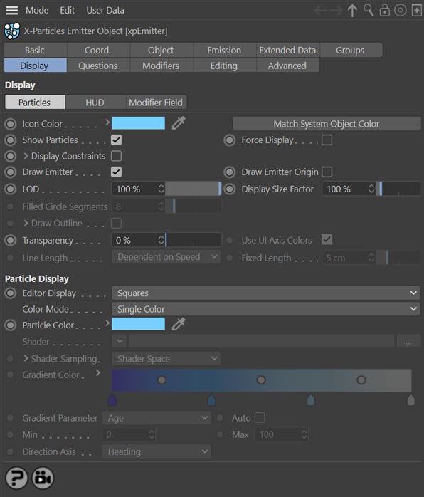
Emitter Display tab: Particles quicktab
This quicktab controls the appearance of particles in the editor and of the emitter itself.
Interface
Parameters
Emitter settings
Icon Color
You can choose any colour for the emitter icon in the viewport. Simply choose the colour from this setting.
This colour will also affect the icon colour when the emitter is in 'Controlled Only' mode. The icon is the same as in previous versions but now changes colour when this parameter is changed.
Match System Object Color
If the emitter is part of a System object hierarchy, you can click this button to set the emitter icon colour to be the same as its parent System object.
Show Particles
If this is unchecked, no particles will be shown. They will still be generated though, so that you can turn them on at any point and have them show on screen.
Force Display
Each particle "knows" its own type - Dot, Sphere, Tick, etc. Normally the particle will be drawn in the editor using its own type. However, if 'Force Display' is checked, all particles will be drawn using the type in the Display tab.
Display Constraints
If constraints are enabled in the xpConstraints object, and this switch is checked, the connections between particles will be displayed in the viewport as thin lines.
If you click the little arrow next to the label 'Display Constraints' a series of colour controls appear which allow you to assign different colours to the different constraint types:
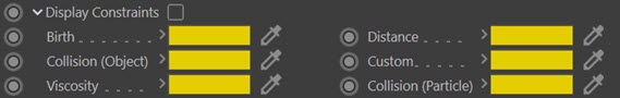
By default all the constraints have a yellow colour but you can change that in this section. You can also generate splines from the constraints using the Trail object and render them using these colours with the X-Particles material.
Draw Emitter
Unchecking this switch will mean that the emitter shape will no longer drawn in the editor. It does not affect anything else and is not used if 'Emitter Shape' is set to 'Object'.
Draw Emitter Origin
If checked, a small cross will be drawn at the centre of the emitter, plus a line pointing along the emitter's Z-axis (this line is not drawn if the shape is set to 'Sphere').
The origin is not shown if the emitter shape is set to 'Object' or 'Defined Emission'.
LOD
LOD is Level of Detail. If you are generating millions of particles, the screen redraw may become very slow, even in fast mode. This is not the fault of X-Particles, it is due to Cinema 4D's screen handling. You can speed up the editor redraw by reducing the LOD to less than 100%. This will cause fewer particles than actually exist to be drawn in the editor, thereby speeding it up.
This does NOT affect the total particles rendered at render time!
Display Size Factor
Changing this value will alter the size of the displayed particles in the viewport. Increasing it can be useful to visualise very small particles more easily. Note that this does NOT affect the particle radius or scale, it is simply an editor display feature. Note that this feature does not work with the Dots or Lines display types.
Filled Circle Segments
If you select the 'Circle (Filled)' display type, you can use this setting to specify the number of segments in the filled circle. A smaller number will result in a faster editor display. This is only a viewport setting and does not affect the rendered result.
Draw Outline
Only used with the 'Circle (Filled)' display type. It causes an outline to be drawn around the circle. By default this outline is a white line, but you can change it by clicking the little arrow next to the 'Draw Outline' table. These parameters then become available:

Outline Color
The colour of the outline.
Outline Multiplier
In earlier versions of X-Particles, the filled circle outline was always the same shade as but slightly darker than the circle itself. You can now alter that setting with this parameter. By default it is set to 0.8, which gives the same result as previously. You can increase or decrease this value to alter the brightness of the outline.
Transparency
Only used if you select 'Sphere' or 'Circle (Filled)' as the particle type.
Use UI Axis Colors
Only used if you select 'Axes' as the particle type. If checked, each axis will be drawn in the same colour used in the world or object axes - normally red, green, and blue for X, Y, and Z. If unchecked, each axis is drawn in the colour specified by the 'Color Mode' setting.
Line Length
Only available if 'Editor Display' is set to 'Lines'. The length of the line can be controlled with this menu. The options are:
Dependent on Speed
The length is calculated from the speed of the particle. The length is the distance travelled by the particle in one frame at its current speed.
Dependent on Radius
The length is the same as the particle radius.
Fixed
The length is a fixed value. This value can be found in the 'Fixed Length' setting.
Fixed Length
Only available if 'Editor Display' is set to 'Lines' and 'Line Length' is set to 'Fixed'. This is the length of the line in 'Fixed' mode and is not affected by the particle speed or radius.
Particle display
Important: the controls in this section are unavailable if there are one or more particle groups in the 'Groups to Use' list in the Groups tab. This is because the display parameters are controlled by the group, not the emitter.
Editor Display
This is the shape of the particle in the viewport. You can choose between:
- Dots
- Ticks
- Axes
- Squares
- Box
- Box (Filled)
- Spheres
- Lines
- Circle
- Circle (Filled)
- Cylinder
- Pyramid
- Arrow
- Arrow (Filled)
- Plane
- Plane (Filled)
- None
'Lines' will show the particles in the same way as the standard Cinema 4D emitter, that is, they are drawn as short lines whose length is dependent on the particle speed. 'Axes' are drawn as three short lines representing the particle's rotation axes (X, Y, and Z). If you choose Spheres or Circle (Filled), you can also set the degree of transparency of the sphere or circle.
The radius of the 'Cylinder' type is derived from the particle radius. Its length is dependent on the particle speed. Particle scale will also affect the length and/or radius of the Cylinder - see the table below.
You should be aware that Spheres are the slowest to draw and Dots are the fastest - important when visualising large numbers of particles!
Choosing 'None' will cause no particles to be drawn (they are still emitted but you can't see them).
Effect of Particle Radius and Particle Scale
Not all display types will change if you change the particle's radius or scale, due to the Cinema 4D API functions used to draw the various display types. This table shows whether the display will change in each case:
| Display Type | Affected by Radius | Affected by Scale |
|---|---|---|
| Dots | No | No |
| Ticks | No | No |
| Axes | Yes | No |
| Squares | No | No |
| Box | Yes | Yes |
| Box (Filled) | Yes | Yes |
| Spheres | Yes | No |
| Lines | No | No |
| Circle | Yes | No |
| Circle (Filled) | Yes | No |
| Cylinder | Yes* | Yes* |
| Pyramid | Yes | Yes |
| Arrow | Yes | No |
| Arrow (Filled) | Yes | No |
| Plane | Yes | Yes |
| Plane (Filled) | Yes | Yes |
* Radius only affects Cylinder radius, not length; Scale X and Y components affect cylinder radius but not length, Scale Z component affects length but not radius.
Color Mode
Note: the particle colour is not only seen in the editor but has an effect on several options at render time - such as the Skinner Shader, the X-Particles Material, the Sprite Shader and other objects: all of these make use of the particle colour.
This drop-down has six options:
Use Emitter Icon Color
With this option, the particles will have the same colour as the emitter icon.
Single Color
The particles all have the same colour, from the 'Color' setting.
Random Color
Particles are assigned a randomly-chosen colour.
Gradient (Random)
A random colour is chosen for each particle from the 'Gradient Color' gradient.
Gradient (Parameter)
The particle colour is chosen from the 'Gradient Color' gradient but the colour chosen is determined by the 'Gradient Parameter' drop-down.
Note that if you choose this mode, the particle colour is controlled by the emitter during the lifetime of the particle. This means that you will not be able to change the particle colour with (for example) a Color Modifier or any other method that changes the colour.
Use Shader
In this mode particles are coloured by a shader placed into the 'Shader' link.
Particle Color
The color of the particle in the viewport. This is used in the editor and in the X-Particles material if that is set to use the particle colour. The default is a light green.
Shader settings
If 'Color Mode' is set to 'Use Shader' there is the option to use a shader to generate the colour. In these modes, the following parameters become available:
Shader
A link field for the shader to use.
Shader Sampling
This menu determines how the shader is sampled.
The options are:
- Shader Space: this will sample the colour at the particle position in the 3D world (this is the default setting)
- Random: this will sample the shader at a different random point in each frame.
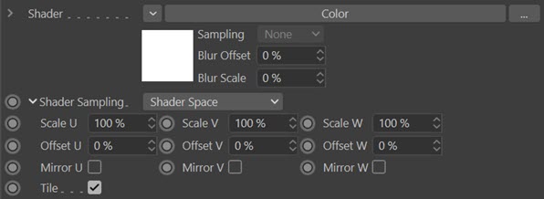
To the left of the word 'Shader Sampling' is a little arrow. Click this to reveal the other parameters.
Scale U, Scale V, Scale W
These three parameters control the size of the shader across the sample space. To put it another way, if the 'Tile' parameter is checked a bitmap will be tiled across the sample space and the number of tiles is controlled by these parameters. If 'Tile' is unchecked the bitmap is simply scaled.
Procedural shaders are scaled using these parameters but the 'Tile' switch has no effect.
Offset U, Offset V, Offset W
The shader will be offset by these amounts in the respective direction.
Mirror U, Mirror V, Mirror W
Checking these switches will mirror the shader across the respective axis.
Tile
If a bitmap is used, checking this switch will cause it to be tiled across the sample space. The number of tiles is controlled by the 'Scale U' and 'Scale V' settings. The switch has no effect on procedural shaders.
Gradient Color
This is used in 'Gradient (Random)' and 'Gradient (Parameter)' modes. By default this is a blue to white gradient.
Gradient Parameter
Note: if you use this mode, then unlike all the other modes the emitter takes control of the particle colour and WILL override anything else you do to change the colour. If you need to alter the colour during an animation you can use this option or you can use the Colour modifier. But if you use the Colour modifier, you must choose another colour mode than this one, or the changes made by the modifier will never be seen.
In 'Gradient (Parameter)' mode the colour the particles are given is taken from the 'Gradient Color' but the precise colour is determined by the chosen setting in this drop-down. The parameters available are:
- Age
- Speed
- Speed (World) - see note 1
- Radius
- Fluid Density - see note 2
- Fluid Density/Velocity - see note 2
- Granular - see note 3
- Fluid Surface
- Mass
- Temperature
- Smoke
- Fire
- Fuel
- Distance Travelled
- Direction - see note 4
- P-P Distance - see note 5
- Rotation - see note 6
For example if the parameter is 'Age', new particles are given the colour from the extreme left of the gradient, particles at the end of their lifespan are drawn in the colour from the extreme right of the gradient.
Notes
- To use 'Speed (World)' you must enable 'World Speed' in the emitter's Extended Data tab.
- 'Fluid Density' and 'Fluid Density/Velocity' will only work if a Fluid FX or PBD Fluid object is active in the scene. The values represent the amount of compression of the fluid.
- 'Granular' is in fact a measure of the number of neighbouring particles. To use it, a Fluid FX object must be present and in the emitter's Extended Data tab (Fluids Data quicktab) the 'Fluid Type' must be set to 'Granular'.
- Direction is an absolute value and there is no min/max setting possible with this. You can select the direction axis to test; this can be either Heading, Pitch or Bank, or all three combined. Particle direction is a vector, with three components to indicate the amount of movement along each axis. Each component can be between 0 and 1 and this is used as an index into the gradient to choose the colour. See below for more details.
- P-P Distance is the distance to the nearest particle from the one to be coloured. It will only work if the 'Nearest Particle Data' switch has been checked so that the particle holds the distance to the nearest other particle.
- This is the rotation of the particle around its own axis. If you chose this option, the 'Direction Axis' setting becomes available and there you can choose which axis to use for the rotation.
Auto
When this switch is checked, the colour gradient is automatically mapped to the range of values in that property. For example, if 'Speed' is chosen in 'Gradient Parameter', the slowest particles are given the colour at the left edge of the gradient, while the fastest ones are given the colour at the right edge. If this switch is unchecked you can choose the range to map to the gradients using the ' Min' and 'Max' settings.
This is not available with the Direction, P-P Distance, or Rotation options. With P-P Distance you must set the range in the 'Min' and 'Max' settings.
Min, Max
The minimum and maximum values to use when the 'Auto' switch is unchecked.
Note: this does not work with the 'Age' parameter. Age is always determined automatically. These settings are also unavailable with the 'Direction' parameter.
Direction Axis
This is used only if 'Gradient Parameter' is set to 'Direction' or 'Rotation'. The options in the menu are the individual axes Heading. Pitch or Bank, or all three axes combined.
Direction
When using this mode, if you select one of the individual direction axes, the emitter will select a colour from the gradient using that axis alone. For example, if 'Heading' is selected and the particle direction has no contribution from the heading, the colour from the left hand end of the gradient is used. If its direction is solely along the positive or negative world X-axis, with no change in pitch or bank, the colour from the right hand end of the gradient is used. The same is true for the Pitch and Bank axes.
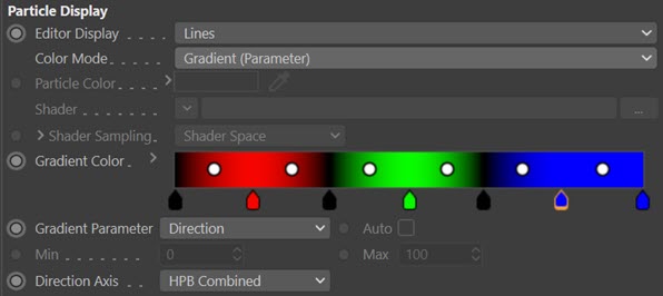
If you select 'HPB Combined' the final colour is made up of contributions from all three axes. The Heading takes the first one-third of the gradient, the Pitch the middle third, and the Bank the last third. The three colours are then added together to make the final particle colour.
Because the three colours are added, you may wish to make sure that if there is no contribution from a particular axis, it does not contribute to the final colour. This can be done by setting the left-hand end of that axis' third of the gradient to black. If you do this for each axis, the final gradient might look like this:
Rotation
 A rotation of zero degrees around the selected axis will return the colour at the left edge of the gradient, while a rotation of 360 degrees will return the colour from the right-hand edge of the gradient. If you choose 'HPB Combined' as the axis, the three individual axis values are added together and converted to the range 0 to 360 degrees.