Emitter Object tab: Emitter quicktab
The first quicktab in the Object tab concerns parameters to do with the shape of the emitter and how particles are emitted from it.
Interface

Parameters
General settings
Emitter Shape
There are seven inbuilt shapes, plus you can use any object from which to emit particles, and a special mode named 'Defined Emission'.
The inbuilt shapes are:
Rectangle
A rectangular emitter with these settings:
- Width: the width of the rectangle.
- Height: the height of the rectangle
- H Angle and V Angle: the angles at which the particles are emitted. Particles are always emitted along the Z-axis of the emitter.
- Edges Only: if checked, particles will only be emitted from the edge of the rectangle.
- 3D: the emitter is drawn as a 3D box, which makes it much easier to see where the particles will go, particularly when the horizontal and/or vertical angles are greater than zero.
- Emitter length: only used when 3D representation is checked. Determines the length of the emitter box along its Z-axis.
Circle
A circular emitter with these settings:
- Radius: the radius of the circle.
- Cone Angle: the angle at which particles are emitted. Particles are always emitted along the Z-axis of the emitter.
- 3D: the emitter is drawn as a 3D cone, which makes it much easier to see where the particles will go, particularly when the cone angle is greater than zero.
- Emitter Length: only used when 3D representation is checked. Determines the length of the emitter cone along its Z-axis.
- Ring Only: if this is checked, particles are only emitted from the circumference of the circle, not its area. The Cone Angle can still be used to generate a hollow cone of particles and a Variation setting can be applied to this to add some variation in the angle.
Ellipse
An elliptical emitter. Settings are the same as for the Circle emitter except that there are two radius settings - H-Radius and V-Radius - for producing the elliptical shape.
Sphere
A spherical emitter with these settings:
- Surface Only: particles are emitted from the virtual "surface" of the sphere, rather than the interior of the sphere.
- Direction: a drop-down menu with these settings:
- Normal: particles move out from an imaginary surface normal of the sphere.
- Random: particles move in a random direction, this gives a chaotic distribution of particles.
- the three axes of the emitter, either positive or negative, in terms of object space.
Box
A cubic emitter with these settings:
- Size: the size of the box in three dimensions.
- Faces Only: if checked, particles are only emitted from the 'surface' of the virtual cube; if unchecked, they are emitted from anywhere on or inside the cube.
- Emit Mode: a drop-down menu with two options:
- Random: the emitting position is chosen randomly.
- Grid: the emitting position is calculated from a grid whose size is set in the 'Grid Size' option; this is a very easy way to emit a cubic grid of particles without the overhead of using a Cube in object mode, for example.
- Grid Size: the size of the grid when 'Emit Mode' is set to 'Grid'
- Direction: a drop-down menu with seven options:
- Faces: the particle direction is along the 'normal' of the virtual face.
- X+, X-, Y+, Y-, Z+, and Z-: the particle direction is along the selected axis of the object (i.e. this is in object space, not world space).
Cylinder
A cylindrical emitter with these settings:
- Radius: the cylinder's radius.
- Height: the cylinder's height (or length, if you prefer!).
- Direction: a drop-down menu with three options:
- Radial: the particle direction is outwards from the axis of the cylinder (no particles are emitted from the ends of the cylinder).
- Standard: the direction is along the Z-axis of the cylinder, just like a Circle emitter except that the particles are emitted from anywhere along the length of the cylinder.
- Bi-Directional: as with the 'Standard' setting except that the direction is either along the Z+ or Z- axes.
- Ring Only: if checked, particles are only emitted from the 'surface' of the virtual cylinder; if unchecked they are emitted from anywhere on or inside the cylinder.
Torus
A toroid emitter with these settings:
- Inner Radius: the inner radius of the torus.
- Outer Radius: the outer radius of the torus.
- Direction: a drop-down menu with these options:
- Away From Centre: the particle direction is along a vector drawn from the torus centre to the particle and moving away from the centre.
- To Centre: the particle direction is along a vector drawn from the torus centre to the particle and moving towards the centre.
- X+, X-, Y+, Y-, Z+, and Z-: the particle direction is along the selected axis of the object (i.e. this is in object space, not world space).
Object
This is described in the section 'Emission from an object'.
Defined Emission
This is described in the section 'Defined Emission'.
Emitter Plane
The direction of particle emission is along the Z-axis of the emitter, which in turn points along the world Z-axis. With this setting you can rotate the emitter to point along the world X- or Y-axis instead. This setting only applies to the Rectangle, Circle and Ellipse emitters.
3D
This setting is only available if the emitter shape is set to Rectangle, Circle, or Ellipse. It shows the emitter as a 3D object which can be very useful if you set the height, width, or cone angles, as it will show the spread of particles from the emitter. Note that this setting has no effect on the actual particle emission.
Emitter Length
This setting is only available if the emitter shape is set to Rectangle, Circle, or Ellipse and the '3D' switch is checked. It is the size of the third dimension of the editor representation. Again, this setting has no effect on the actual particle emission.
Offset X & Y
If you select a Rectangle, Circle, or Ellipse emitter, then normally you want particles to be emitted from the area of the emitter, with the starting position set randomly. However, if you only generate one particle, if for example you are using the emitter in conjunction with a Trail object and a Sweep object, then you may find that you would like the particle to be emitted from the centre of the emitter so that you know exactly where it will originate from. Unchecking this switch will ensure that all particles start from the centre of the emitter. Note that this only applies to Rectangle, Circle, and Ellipse emitters.
Offset Origin
If you look closely at the particle starting position, you will see that each particle starts at a small distance ‘in front of’ the emitter. This is a consequence of how the emitter works (you can also see it with the standard Cinema 4D emitter). If that causes a problem, you can use this slider to offset the starting position so that particles emit ‘behind’ the emitter, or even well in front of it. Typically, only a few screen units are needed to achieve the required effect.
Retiming
This setting can be used to speed up or slow down the emitter. For example, suppose you have an emitter which uses a particle speed of 150 units and a particle lifespan of 90 frames. With this setting at 100% (the default) the particles will reach a certain point in the scene at 90 frames and will then die.
If you now increase this value to 200%, the particles will travel faster and reach the same point at 45 frames, and will then die, also at 45 frames. Reducing the value below 100% will make the particles travel slower and die later. But when they die they will still have reached the same position they would have done if this value was at 100%.
Note that if you want to spin the particle using the 'Simple Spin' feature in the emitter, the rate of spin will not be affected by the retiming (in other words, the spin rate stays the same). If you use a Spin modifier, however, the rate of spin is affected by the retiming.
Emission from an object
X-Particles can emit from almost any Cinema 4D object. The exception is a null object: null objects cannot be used as an emission source. Null objects with child objects can be used, however. Almost every other object can be used, including lights, C4D generator objects, and objects which are themselves being generated by a Generator, Sprite, or Trail object and another emitter.
Important: if you emit from an object the object scale set in the Attribute Manager MUST NOT contain negative values. You can scale the object using the Scale tool or change its scale in the Coordinates manager using negative values, but in the object attributes the scale must all be positive values. This is currently a limitation.
When you select an Object as the emission shape, the interface changes and you see this:
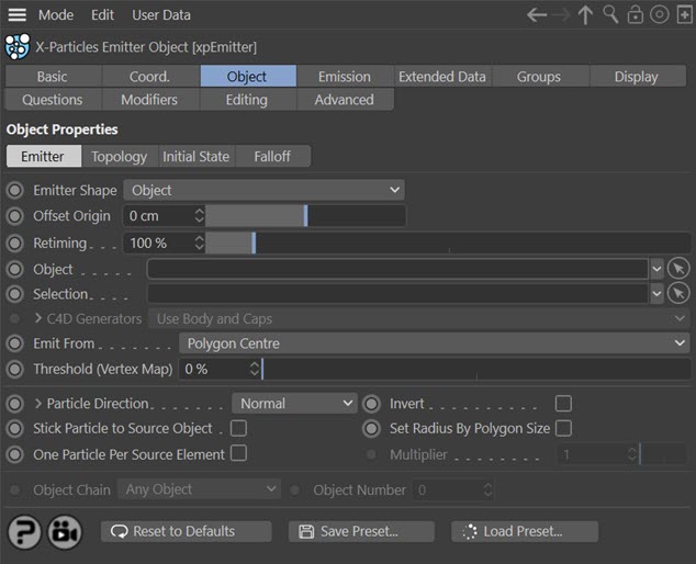
Note that additional quicktabs have now become available. These vary depending on the option selected in the 'Emit From' setting. You have a number of parameters to set. These are:
Object
A link field into which you drag the object to emit particles from. If this is a null object with child objects, the actual emission object will be selected according to the 'Object Chain' setting.
Selection
A polygon selection tag, point selection tag, edge selection tag, or vertex map can be dragged into this field; particles will only be emitted from the selected polygons, points, or edges on the linked object.
However, what happens if the 'Emit From' setting does not match the selection tag? Suppose you want to emit from 'Polygon Centre' but supply a point selection tag. How is this handled?
If the linked object is a polygon object, and 'Emit From' is set to 'Polygon Centre' or 'Polygon Area', and you enter a point selection or edge selection tag here, X-Particles will attempt to convert the point (or edge) selection into a polygon selection. If it succeeds, particles will be emitted from the resulting selected polygons; if it fails, then particle emission will be from any randomly-selected polygon on the object.
If you try to emit from the object's vertices and supply a polygon or edge selection, X-Particles will try to convert this to a point selection and emit from the resulting selected points. If it fails it will emit from a randomly-selected point on the object.
Vertex maps are only used when the object is a polygon object (or can be converted to one internally by X-Particles) and 'Emit From' is set to points. In all other modes vertex maps are ignored.
If the object has neither points nor polygons, selection tags are ignored.
X-Particles can use the selection tags from the Voronoi Fracture object present in Cinema 4D R18 and later. You can use any of these tags in the usual way.
C4D Generators
This drop-down menu determines what part of a C4D generator object the particles will be emitted from. It is only available if the source object is a Cinema 4D generator object (i.e. Lathe, Sweep, Extrude or Loft but not including the Subdivision Surface object). It has three options:
Use Body and Caps
Particles are emitted from the body of the object and its caps.
Use Body Only
Particles are only emitted from the body of the object and not its caps.
Use Caps Only
Particles are not emitted from the body of the object but only its caps.
Refining particle emission from generator object caps
If you click the little arrow to the left of the 'C4D Generators' parameter, you can refine the caps emission if you selected anything other than 'Use Body Only'. Four switches are then available:

These correspond to the special selections that are formed on a C4D generator object - C1 and C2 are the polygons/points making up the main part of the cap, while R1 and R2 are the polygons which form the 'rounded' part of the cap, and are only available if filleted caps are turned on in the C4D generator objects.
Check any of these switches to emit from that part of the cap.
Emit From
This determines the source of the emitted particles. You can choose from:
- Polygon Centre: particles are emitted from the centre of the object’s polygons. Polygons are weighted (that is, larger polygons are more likely to emit particles than small polygons).
- Polygons: particles are emitted from a random position on the polygon faces. However, unlike 'Polygon Centre' and 'Polygon Area' the polygons are not weighted by size. This results in a true random distribution across all the polygons so that very small polygons receive as many particles as very large ones.
- Polygon Area: particles are emitted from a random position on the polygon faces. As with 'Polygon Centre', the polygons are weighted by size.
- Texture: emission from the object is controlled by a texture. This is the same as 'Polygon Area' mode but with additional settings for the texture.
- Object Color: emission is controlled by the object's colour.
- Illumination: emission from the object is determined by the illumination of the surface by specific scene lights.
- Points: particles are emitted from the object’s points. There is support for the Vertex Color tag in Cinema 4D R18 and later - see below.
- Edges: particles are emitted from the object's edges (polygon objects only) or from along the length of a spline.
- N-gon Centre: particles are emitted from the centre of any n-gons in the object. As with 'Polygon Centre', the n-gons are weighted by size. There are certain limitations in this mode, see below.
- Object Position: particles are simply emitted from the object’s world position. Some objects, i.e. the MoGraph Cloner, Matrix and Fracture objects, and the Voronoi Fracture object (Cinema 4D R18 and higher) are special cases when emitting from the object position, especially when using MoGraph selection tags. See the notes below for full details.
- Object Volume: particles are emitted from a random point inside the object. If you set the particle speed to zero you can use this setting to fill an object with particles
- Voxel Grid: the object is divided up into a grid of square cells, and a particle is emitted from the centre of the cell. This is described more fully below.
Threshold (Vertex Map)
 If you add a vertex map tag to the 'Selection' field then you can set a threshold for the strength of the vertex map. For example, if you set this field to 20%, particles will only be emitted from the vertex map where the strength is higher than 20%. By default this is set to zero so particles will be emitted wherever the strength is greater than zero.
If you select 'Points' then this option becomes available:

Vertex Color Tag
In Cinema 4D R18 and above, there is a new vertex color tag allowing you to paint an object's vertices with colour. If an object has such a tag, and you emit particles from its vertices, the particles will take their colour from the vertex they are emitted from.
If the object already has one Vertex Color tag, the particle colour will automatically be taken from it. But if there are multiple Vertex Color tags on the object, you can choose which one to use by adding it to this link field.
Edge emission: polygon objects
If you choose 'Edges' as the emission source, and the object is a polygon object, two further options become available:

Even Distribution
By default the emission point along the edge is chosen randomly, which can lead to irregular distribution of particles. To get an even distribution, check this box. The particles are then spaced evenly according to the 'Spacing' setting.
If the object is a spline, this parameter functions slightly differently - see below.
Spacing
This number indicates how many emission points there will be along the edge. It is not a percentage value or an actual distance in screen units, but is used together with the edge length to determine the number of emission points. This ensures that the spacing of the emitted particles is always the same, regardless of the length of the edge. The higher the number, the greater is the space between the emitted particles.
For any edge, if the value is greater than the length of the edge, particles will only be emitted from the two ends of the edge and not along its length.
If the object is a spline, this parameter functions slightly differently - see below.
Edge emission: splines
If the object is a spline, several more options are shown:
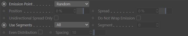
In this mode, particles are emitted from the spline length rather than just its vertices.
Emission Point
This drop-down has two settings:
- Set: the position along the spline to emit from, in terms of a percentage of the spline's length. That percentage is given in the 'Position' field.
- Random: particles are emitted from positions randomly chosen along the spline.
Position
If 'Emission Point' is set to 'Set' then the emission point along the spline is given as a percentage of the spline's length.
Spread
Only available if 'Emission Point' is set to 'Set'. This will spread the particles around the emission point. For example, a position of 0% with a Spread of 10% will emit particles between -5% and 5% along the spline. (Note that '-5%' along the spline is the same as 95% along its length.)
Unidirectional Spread Only
If you do not want the 'Spread' value to be used either side of the emission point, check this switch. Then a position of 0% with a Spread of 10% will emit particles between 0% and 10% along the spline.
Do Not Wrap Emission
Checking this switch will confine emission between 0% and 100% of the spline length. Suppose you set 'Position' to 0% and 'Spread' to 10%, with 'Unidirectional Spread Only' checked. Then you animate 'Position' by keyframing it. When the position reaches 91% or higher, by default the particles which would then be emitted at 101% of the length of the spline will be emitted at a position 1% along it, giving the effect that the particles wrap around the length. If you don't want this, so that emission ceases when the position reaches 100%, check this switch. It will prevent the wrap round effect from occurring.
Use Segments
This drop-down has two settings:
- All: in a multi-segment spline, a particle will be emitted from a randomly-chosen segment.
- Select: in a multi-segment spline, all particles will be emitted from the segment given in the 'Segment' setting.
Segment
If 'Use Segments' is set to 'Select' the segment to use is given in this field. Note that the segments are zero-based, that is, the first segment has the number 0; if there are 5 segments, the last segment has number 4.
It is up to you to make sure that the value you specify is a valid one. If the spline has 5 segments and you enter '5' or higher in this field, no particles will be emitted.
Even Distribution
This option is only available if 'Emission Point' is set to 'Set'. If this switch is checked, the 'Position' setting is ignored and particles are spaced evenly along the spline. You can still use the 'Spread' setting to produce small clumps of particles at regular intervals. The 'Spread' setting may need to be very small (less than 1%), depending on the spacing, otherwise the particle clumps may overlap and the distribution will seem to be random.
Spacing
This number indicates how many emission points there will be along the spline. It is not a percentage value or an actual distance in screen units, but is used together with the spline length to determine the number of emission points. The higher the number, the smaller is the space between the emitted particles.
Note that the 'Spacing' setting works in the opposite fashion for splines as it does for edges on polygon objects.
N-gon Centre
To Cinema, an n-gon is just a group of polygons, either quads or tris, arranged in a special format. When an object contains an n-gon, what X-Particles sees are simple polygons. Therefore, if you emit from 'Polygon Centre' particles will be emitted from the centre of each of the polygons in the n-gon.
If what you need is for the particles to be emitted only from the geometric centre of the n-gon, select 'N-gon Centre' from the 'Emit From' drop-down. Now particles will only be emitted from the centre of the n-gon.
There are certain limitations on the emitter when you do this, which are:
- particles are only emitted from n-gons; quads and tris are ignored, so if there are no n-gons in the object, no particles are emitted
- if there is a hole in the n-gon, it is possible the geometric centre of the n-gon is located in the hole, and that is where the particles will originate; there is nothing we can do about this, as the n-gon centre is calculated by the Cinema API
- only polygon selections are supported, vertex or edge selections or vertex maps are ignored
- if a polygon selection contains both n-gons and regular polygons, only the n-gons are used and no particles will be emitted from polygons which are not part of an n-gon
- the options 'Stick Particle to Source Object' and motion inheritance are not supported
Max. Retries
This setting only appears if you choose 'Object Volume' or 'Voxel Grid' as the emission type. In both cases the emitter must determine if the chosen emission point is within the object. If it is not, another point is selected. This is very easy with objects such as cubes, but more difficult with spheres, pyramids, etc. Then it may take several attempts to find a suitable emission point. With very irregular objects, many retries may be necessary and that number could be so large that it would significantly slow down the animation.
For this reason, a limit is placed on the maximum number of attempts to find an emission point. If this number is exceeded, no emission occurs. If you find that you are getting areas in the object where no emission seems to occur, you can increase this setting, but it may slow down the particle emission.
Particle Direction
This determines the initial direction of each emitted particles. The choices are:
- Phong Normal: particles are emitted along the phong normal of the selected point on the surface. If 'Points' are chosen as the emission source, the vertex normal is used instead.
- Normal: particles are emitted along the face normal (for polygon centre/ polygon area modes) or the vertex normal (for point mode). This only applies to polygon objects. For point objects such as splines, which do not have normals, the particles are emitted radially away from the spline.
- Random: particles are emitted in a completely random direction.
- X+ Axis/X- Axis: particles are emitted along the object’s positive or negative X axis (NOT the world X-axis)
- Y+ Axis/Y- Axis: particles are emitted along the object’s positive or negative Y axis (NOT the world Y-axis)
- Z+ Axis/Z- Axis: particles are emitted along the object’s positive or negative Z axis (NOT the world Z-axis)
Invert
If checked, this switch inverts the selected direction.
Perpendicular to Normal
If you click the little arrow next to the 'Particle Direction' label, these controls appear:
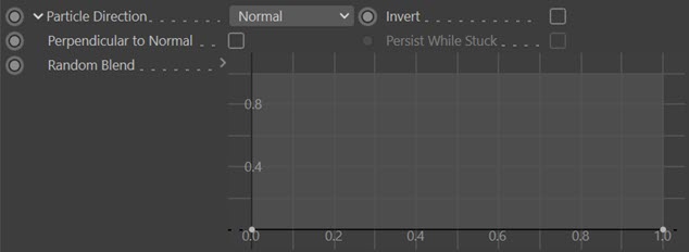
If the 'Perpendicular to Normal' switch is checked, and 'Particle Direction' is set to 'Normal' (NOT 'Phong Normal') particles are emitted at a randomly-selected direction perpendicular to the surface normal.
Note that this will only work when 'Emit From' is set to certain modes - 'Polygon Centre', 'Polygon Area', 'Texture', and 'Object Color'.
Persist While Stuck
If this switch is checked, and 'Particle Direction' is set to 'Normal', and particles are stuck to their source object, the particle direction is updated as the surface normal changes.
This can be useful if particles are stuck to an object which is being deformed with an animated deformer. The animation might cause the surface normal to change, but if this switch is not checked the direction of the particle will remain as it was when the particle was created. If this switch is checked the direction will be updated as the normal changes. To see the result, you would also enable rotations in the emitter's Extended Data tab, and set 'Rotation Mode' to 'Tangential'. This results in a very natural, organic appearance. In this scene, particles are emitted from a sphere with an animated Displace deformer to distort the surface, and the particles are stuck to the sphere.
On the left the 'Persist While Stuck' switch is off and you can see that, although the surface normal is altered, the particle orientation does not change. On the right, this switch is enabled so that the particle orientation conforms to the surface normal:
This switch is not available when 'Emit From' is set to certain modes. In addition, 'Particle Direction' must be set to 'Normal' (not 'Phong Normal') and 'Stick Particle to Source Object' must also be enabled.
Random Blend
Firstly, note that this is only usable when 'Emit From' is set to certain modes - 'Polygon Centre', 'Polygon Area', 'Texture', 'Object Color' and 'Illumination'. Also, 'Particle Direction' must be set to 'Normal'. It is not available if 'Perpendicular to Normal' is checked.
You can use this spline control to blend the calculated particle direction with a random element. For example, when emitting from polygon centres, you can obtain this effect:
Stick Particle to Source Object
If this switch is checked, once the particle has been generated it will stick to the object which acted as the emission source. The particles will stay stuck even if the object is animated. You can unstick them at any point using an Unstick Particles Action or a Negate modifier.
Note: for this function to work, the object must be something other than a null object or one which, when collapsed, results in a null object with child objects.
Set Radius By Polygon Size
This switch is available when 'Emit From' is set to 'Polygon Centre', 'Polygons', 'Polygon Area', 'Texture' or 'Illumination'. If checked, the particle radius is determined by the size of the polygon from which it is emitted. To see different particle radius values, you must set the radius variation parameter in the Emission tab to something other than zero. The minimum radius used will be the radius setting minus the variation value; the maximum radius will be the radius setting plus the variation value.
The smallest polygons will emit particles with the smallest radius and the largest polygons will give the largest radius. Note that if all the polygons are the same size, all the particles will have the same radius, regardless of any variation you may have entered.
Radius can also be determined by the texture of the object. If you have checked this switch and also opted to control the radius by texture, the texture will take precedence and this switch is ignored.
One Particle Per Source Element
This switch is only available when 'Emit From' is set to 'Polygon Centre', 'Points', or 'Object Position'. It forces the emitter to emit one, and only one, particle for each element (polygon or point) in the object, or in the case of 'Object Position', from the position of each object in a chain of objects.
If this switch is enabled, the Birthrate parameter in the Emission tab is ignored, since the birthrate now depends on the number of polygons or vertices in the object. Note that it may result in a large number of particles being generated. For example, a Birthrate of 100 when this option is off would generate 100 particles per second - or 3 to 4 per frame if the frame rate is 30 fps. But if this option is on, and the source object has 100 vertices, this will result in 100 particles being generated per frame - equivalent to a normal birthrate of 3,000 per second.
Multiplier
If the emission mode is set to 'Object Position' and 'One Particle Per Source Element' is enabled, this setting becomes available. Normally, using 'One Particle Per Source Element' does exactly that, but if you want to emit particles from the position of each object in a Mograph Cloner, this restricts you to one particle per clone per frame. Using this parameter, you can multiply the number of emitted particles; for example, setting it to 50 will emit 50 particles per clone per frame.
Object Chain
If you drag a generator-type object, such as a Cloner or Array object into the Object link field, the emitter converts the object to a polygon object internally before calculating where to create the particle. However, generators can create a chain of objects when converted. For example, an Array with default settings and a sphere child object will, when converted, result in a null object with eight child spheres. Which of the child spheres should be selected to emit from?
This drop-down menu gives you five choices:
- Use First Object: the first object in the chain is used
- Use Last Object: the last object in the chain is used
- Use Specific Object: the object given in 'Object Number' is used
- Any Object: an object is selected randomly from the chain
- Connect Objects: the child objects are joined into one large object and that is then used as the emission source
Note that using these options will affect the particle direction if that is set to use one of the object axes. For example, suppose you set the particle direction to the positive X-axis. If you now select any of the first four options in the 'Object Chain' list, the particles are emitted along the object's positive X-axis, not the 3D world X-axis. This is consistent with the options in 'Particle Direction' above. But what if you choose 'Connect Objects'? In that case the various objects could all have different rotations so an object axis cannot be used; in this case, the world X-axis would be used instead.
Be aware that the Voronoi Fracture object in Cinema 4D R18 and above, when converted, actually results in a null object with one polygon object child for each fractured piece of the original object. To emit from all the fractured pieces each frame therefore, you should use the 'Connect Objects' setting. If you use the default 'Any Object' setting, particles will be emitted from one randomly-chosen fractured piece each frame.
MoGraph Selections
X-Particles contains additional support for the MoGraph Selection tag. When using a Cloner, Matrix, Fracture or Voronoi Fracture object as the object to emit from, you can select some of the clones using the MoGraph Selection tool, which automatically creates a selection tag. What happens then depends on the object, the emission mode, and the 'Object Chain' setting:
| Cloner, Fracture, and Voronoi Fracture objects | |||
|---|---|---|---|
| Emission mode | Object Chain setting | MoGraph Selections | Result |
| All except object position | First Object, Last Object and Specific Object | Ignored | Emission from the specified object |
| Any Object | Ignored | Emission from a randomly-chosen clone each frame | |
| Connect Objects | Supported | Emission from all clones each frame (assuming the birthrate is high enough) | |
| Object position | First Object, Last Object and Specific Object | Ignored | Emission from the position of the specified object |
| Any Object | Supported | Emission from a randomly-chosen clone each frame | |
| Connect Objects | Ignored | Emission from the position of the cloner itself - in this mode all clones are amalgamated and the composite object has the cloner's position | |
| Matrix object | |||
| Object position (other modes not valid) | First Object, Last Object and Specific Object | Ignored | Emission from the specified object |
| Any Object | Supported | Emission from a randomly-chosen clone each frame | |
| Connect Objects | Ignored | No emission (the result of the connection is a null object, which cannot be emitted from) | |
You can see from this that:
- the only valid emission mode for a Matrix object is 'Object Position' - all others will result in no particles being emitted, because there is nothing to emit from
- MoGraph selections are supported only in 'Connect Objects' mode for the Cloner, Fracture and Voronoi Fracture objects, and for 'Any Object' when emitting from a Matrix object
- when 'Any Object' is selected, the emitter will choose one of the clones to emit from each frame, rather than emitting from all of them simultaneously
Note that you don't need to drag the Mograph selection tag into the 'Selection' field in the emitter (you cannot, in fact, do that).
That is all you need to do. Particles will then be emitted only from the selected clones. It is possible to use Xpresso to change which clones are selected, allowing you to emit from clones in sequence, for example.
Object Number
The number of the object in an object chain to use if 'Object Chain' is set to 'Use Specific Object'. The number is zero-based, i.e. the first object has number 0. It is up to you to make sure that this number is valid. If you want to emit from a cloner which produces 10 clones, and you specify 10 or higher no particles will be emitted (the last object in the chain will have number 9).
Voxel grid emission
A voxel is simply a cubic cell of fixed size, representing a cube of 3D space. Any object can be divided up into voxels, the number of which will depend on the size of the voxel. You can use this mode, for example, to divide an object into a number of small invisible cubes, each containing a single particle.
When you select this emission type, you see the additional settings:
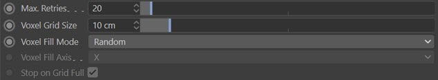
Max. Retries
See above for discussion of this setting.
Voxel Grid Size
This is the size of the grid in scene units. It determines how many voxels are used and therefore the number of generated particles. It is not always easy to decide what size this should be. For example, a grid size of 10 in a Cube primitive of 200 units on each side will result in a total of 8000 voxels (200 / 10 = 20, 20 cubed = 8000). But for an irregular object deciding on the correct size may take a certain amount of trial and error.
Caution: setting the grid size too small may require a very large number of particles to fill the grid!
Voxel Fill Mode
This drop-down has two settings:
- Random: voxels are selected randomly and a particle emitted from that voxel.
- Ordered: the voxels are used in order. You can select the order in which to use the voxel grid with 'Voxel fill axis' setting.
Voxel Fill Axis
if 'Ordered' fill mode is selected, the grid can be filled along the X, Y, or Z axis using this drop-down menu. If you set the particle speed to zero, and check 'Stop on Grid Full' you will end up with the object filled with a grid of particles.
Stop on Grid Full
This is only available if 'Ordered' fill mode is selected. Emission of new particles will stop when a particle has been emitted from each voxel.
Defined emission
Defined Emission enables you specify exactly where and how many particles will be emitted using a variety of adjustable patterns. When you select this option, the interface changes significantly:
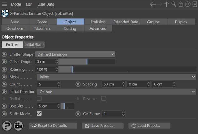
Mode
This enables you to choose the pattern to use. Currently there are three (Inline, Circular, and 3D Grid, plus a fourth special mode for use with the Fragmenter object. The three pattern modes appear in the editor like this:
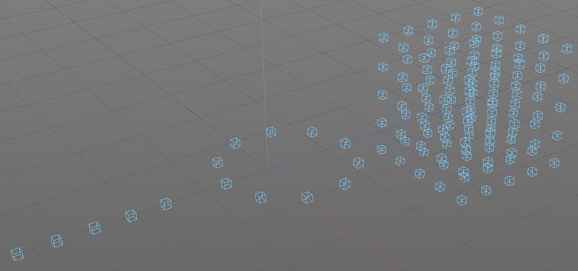
In each mode, one particle will be emitted from every box, each frame.
Inline mode
There are two settings:
- Count: the number of boxes in the line
- Spacing: the spacing between them, on the X, Y, and Z axes
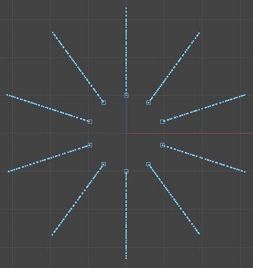
Circular mode
There are six settings:
- Count: the number of boxes in the circle
- Radius: the circle's radius
- Repeat: the number of circles; these will be stacked on top of each other along the Y-axis of the emitter
- Repeat Spacing: the distance between the circles if there is more than one
- Slice Start and Slice End: by default the circle is the full 360 degrees, but you can use these settings to make a part-circle from (for example) 90 to 270 degrees, or any other combination
3D Grid mode
There are two settings:
- Count: the number of boxes in the grid along each of the three axes
- Spacing: the spacing between them, on the X, Y, and Z axes
Fragmenter List
This option causes the emitter to work in conjunction with a Fragmenter object in 'Objects' mode. Please see the documentation for the Fragmenter for details.
Initial Direction
This drop-down sets the initial direction of the particles. This can be:
- Random: each particle has a randomly-assigned direction
- X+/X-: particles move along the positive or negative X axis
- Y+/Y-: particles move along the positive or negative Y axis
- Z+/ZX-: particles move along the positive or negative Z axis
Radial
This switch is only available in Circular mode. It causes the 'Initial Direction' setting to be ignored and the particles emitted in a radial fashion outward from the boxes like so:
Reverse
This switch is only available in 'Circular' mode and if the 'Radial' switch is checked. It causes the particles to be emitted inwards towards the centre of the circle.
Box Size
The size of the boxes in the editor. These are never rendered.
Static Mode
One of the most useful ways to use defined emission is for the emitter to emit one particle for each box on just one frame. By linking the emitter to a Generator or Sprite object, you then have a simple cloner, but with the advantage that the particles (and therefore the objects) can be controlled by the X-Particles particle engine.
Checking this box will set this up for you automatically. It will set the emission to occur on one frame, which you specify in the 'On Frame' field.
On Frame
The frame to emit on if 'Static Mode' is checked.
Instance
If you select 'Instance' from the 'Emitter Shape' menu, these settings are available:
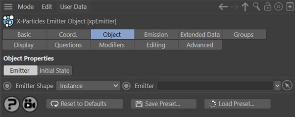
Using this shape forces the emitter to be an instance of another emitter. In that case, settings such as speed, editor shape, colour, etc. are all derived from the source emitter, not from the instance emitter,
Why would you want to do this? With a regular emitter, if you make it a child of a Cinema 4D Cloner or Array object, nothing happens - the original emitter will work as normal but the clones/copies do not work at all. But if you make an instance emitter the child of a Cloner or Array, all the clones will work as normal - that is, as copies of the source emitter.
Emitter
Drag and drop the source emitter to use into this field. If the field is empty, the emitter will not emit any particles.