Flow Field Object
 The FlowField has undergone an extensive rewrite for this version of X-Particles and its interface has changed significantly.
Important: due to the very extensive changes to xp FlowField over previous versions, it it not possible to import existing scenes using an xpFlowField and retain the saved settings. Any existing xpFlowField object will therefore revert to the default parameters with a single 'Random' layer.
A flow field (sometimes termed a velocity field) uses an array of vectors to control the movement of particles within it. It is especially useful for such things as chaotic movement, fluid movement, movement controlled by procedural formulas, noise-controlled movement and so on.
A flow field is an area of 3D space divided up into a grid of smaller cubes or cells. Each cell contains a parameter which is a velocity vector - that is, a direction and speed of movement. When a particle enters a cell, its direction is transformed to match that of the vector in the cell. As it moves through the field it will enter other cells containing velocity vectors that change its movement again. This will continue until the particle leaves the field.
You can see from this that the crucial factor in a velocity field is the arrangement of the vectors. These could be completely random or they could force the particle to follow a path such as a sine wave. The Flow Field object offers a number of ways to set these vectors.
By default the Flow Field object looks like this in the viewport:
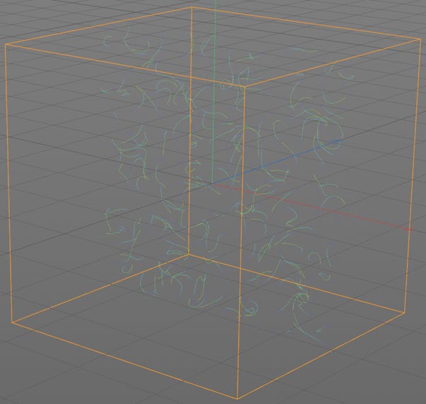
The orange box is the volume enclosed by the field and the wavy lines inside it are the vectors (the vector display can be turned off if desired). By default, the vectors are shown in the XY plane only for clarity. To see all the vectors, choose 'Voxels' from the 'Mode' menu in the Display tab.
Interface
The object's interface includes these sections:
For the buttons at the bottom of the interface and the 'Groups Affected', 'Mapping' and 'Falloff' tabs, please see the 'Common interface elements' page.
Parameters: Object tab
General quicktab
Enabled
Uncheck this switch to disable the object.
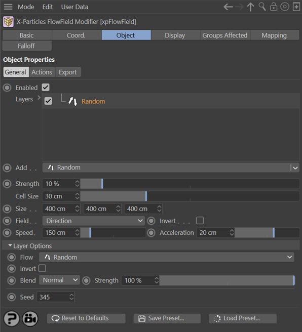
Layers
The FlowField object can now work with multiple layers which are blended together for the final result. This gives a much more powerful and customisable effect than the previous version.
To add layers to this list, select the layer type from the 'Add' menu button below the list. You can add as many layers as you wish.
At any point you can temporarily disable a layer by unchecking the checkbox on its left. You can also delete layers by selecting a layer and pressing the Delete key, or by right-clicking a layer and choosing 'Remove' or 'Remove All' from the context menu.
Each layer has a different set of options. To edit these options, click a layer to select it, and then they will appear in the 'Layer Options' section.
You can also reorder the layers by dragging them above or below other layers, and for blending purposes the layer order is important.
Add
Use this menu button to add layers to the 'Layers' list. The following layers are available, each with its own options:
- Random
- Shader
- Target
- Along Spline
- To Spline
- Surface Tangent
- Surface Normal
- Particles
- Turbulence
- Curl
- ExplosiaFX
- Import
- Fields
- Surface Flow
Strength
The overall strength of the flow field. The higher this value, the greater the effect on the particle.
When a particle enters a cell, its direction will change to that of the vector in the cell. But this will result in an abrupt change of direction which may be undesirable. This parameter controls how quickly the direction changes; low values cause a slow change and a smoother curve but with low values the particle may leave the cell and enter another before the change in direction is completed.
The value in this parameter will depend on a number of things including particle speed, cell size, and how desirable it is that the particle fully completes its change of direction before leaving the cell.
Cell Size
The size in scene units of the individual cells. Each cell is a cube and this will not change, whatever the size or resolution: the cell is the same dimensions on each side.
Size
The size of the Flow Field box in screen units. You can also change the size by dragging one of the resizing handles of the object in the viewport.
Note that as you increase or decrease the size the number of cells along that axis will change
Field
This setting determines what the flow field does to the particle. It has three options:
Direction
The flow field will alter the particle direction but not its speed. The rate of changing direction will depend on the 'Strength' parameter.
Velocity
The flow field will alter the particle direction and its speed, up to a maximum speed which is set in the 'Speed' parameter. The rate of changing direction and speed will depend on the 'Strength' parameter.
Acceleration
The flow field will alter the particle speed, and the speed will continue to increase while the particle remains in the flow field box. The rate of speed increase is set in the 'Acceleration' parameter and the direction will only change if the 'Acceleration' parameter is greater than zero. The rate of changing direction and speed will also depend on the 'Strength' parameter.
Invert
If checked, this switch will invert any direction change caused by the flow field.
Speed
If 'Field' is set to 'Velocity' this is the maximum speed the particle will reach. If this value is lower than the particle's current speed, it will slow down to that speed.
Acceleration
If 'Field' is set to 'Acceleration' this is the rate of speed change while the particle remains within the flow field box.
Negative values are possible and have the effect that the particle speed will slow to zero then accelerate again but with a reversed direction.
Layer Options
Each layer type has different options and these are described in this section.
Common settings
All layers have the following settings:
Flow
This menu is the same as the 'Add' menu below the 'Layers' list. It enables you to change from one type of layer to another without having to delete the layer and add a new one.
Invert
If checked, the vectors generated by this layer are inverted.
Blend
This is a powerful option which lets you blend layers together. Each layer is blended with the one below it in the list. Layers are evaluated from the bottom of the list upwards, so if you have three layers, layer 3 at the bottom is not blended with anything (as it has no layer below it); layer 2 is blended with layer 3 and finally layer 1 is blended with the result of blending layers 2 and 3.
When two layers are blended they use the algorithm selected from this menu, which can be different for each layer, and the blend is weighted by the 'Strength' setting in the upper layer of the two.
There are several different algorithms to choose from. As an example, assume that we have two layers like this:
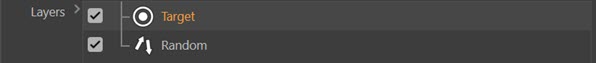
Each layer will generate its own set of direction vectors. What will happen if these are blended together using different algorithms?
Note that in all cases the blend takes place using the 'Strength' setting from the 'Target' layer to weight the blend.
Normal
The vectors are simply blended using the strength setting in the 'Target' layer. If the strength is 100%, the 'Random' layer vectors make no contribution to the overall result, which is entirely determined by the 'Target' vectors. If the strength is zero, the 'Target' layer vectors make no contribution to the overall result, which is entirely determined by the 'Random' vectors.
Min
The smaller of the two vectors from the 'Target' and 'Random' layers is blended with the 'Random' vector.
Subtract
The 'Target' vector is subtracted from the 'Random' vector and the result is blended with the 'Random' vector.
Multiply
The two vectors are multiplied together and the result is blended with the 'Random' vector.
Max
The larger of the two vectors from the 'Target' and 'Random' layers is blended with the 'Random' vector.
Add
The two vectors are added together and the result is blended with the 'Random' vector.
Strength
This is the blend weight used to blend a layer with the layer(s) beneath it. A value of zero will always result in the upper layer making no contribution to the final vector, but a value of 100% does NOT mean that only the upper layer is used for the vectors, except when 'Blend' is set to 'Normal'.
Important points to note
1. Remember that there are only two layers in the above example. If there was a third layer below 'Random' it is the result of blending 'Random' with the layer below it that would then be blended with the 'Target' layer.
2. For the bottom layer in the list, or if there is only one layer, the 'Blend' and 'Strength' settings have no effect and are ignored.
Random layer
This layer simply generates random vectors. There are no other settings.
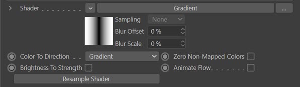
Shader layer
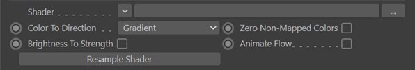
In this layer a shader is used to generate vectors. These additional options appear:
Shader
Use this link to specify a shader to use here. By far the most useful are shaders that can be animated, such as Noise, but you can use any shader.
If you set 'Color to Direction' to 'Gradient', you must enter a gradient shader here, or the layer will have no effect.
The parameters of the shader can have very significant effects on the result. For a Noise shader, for example, changing the noise type, octaves, space, scale, animation speed, cycles, high and low clipping, brightness and contrast will all markedly affect the flow!
Color To Direction
The default setting is 'Gradient'. This will use the brightness of the gradient knots to determine the direction. The vectors will be oriented to the brightest colour, but the actual colour is not relevant. If there is no brightness gradient - that is, all the colours are the same brightness - it will have no effect.
Some interesting results can be obtained. For example, this gradient:
Produces this effect:
The other options address the problem of converting a colour into a direction vector. The colour from the shader is sampled and produces a result from 0 to 1 for each colour component (red, green or blue).
We use the convention that red represents movement along the X-axis, green along the Y-axis, and blue along the Z-axis. The direction can either be positive or negative, but colour values are always positive, so to obtain vectors which can point along either the positive or negative axes, the colour is remapped from a range of 0 to 1 to a range of -1 to 1. This means that a colour with red set to 100% will result in a direction along the positive X-axis, while no red at all is movement along the negative X-axis. For example, a noise shader whose colours are set to red and black would result in vectors pointing along the X-axis (positive or negative) but not along the Y- or Z-axes since there is no green or blue in those colours..
If you set 'Color To Direction' to its default value of 'Red, Green and Blue' each colour component is remapped to give a value between -1 and 1; these values are combined to give the final direction of the vector. If you change the menu to 'Red Only' the red component is remapped, but the blue and green components remain at their sampled values - and these are always positive values.
With a colour such as a yellow-green (in RGB terms it could be 0.75, 1.0, 0.0) and assuming both colours are mapped, then the red value will be mapped to the range -1 to 1. In this case the X-axis component of the direction vector will be +0.5 and the Y-axis component will be 1.0.
If you leave red unmapped by changing this menu to 'Green Only', red will have a greater effect on the X-axis component because its unmapped value is +0.75. To remove any contribution at all from the red colour, you can check the switch 'Zero Non-Mapped Colours' which would cause the red component to be zeroed.
In that case the red component will no longer have any effect and the vectors will all point along the positive Y-axis with no direction along the X-axis at all. You can zero unmapped colours with any of the combinations of colours in the menu with the exception of 'Red, Green and Blue' since in that case all the colours are mapped and there are no unmapped colours to zero.
With a single colour it is easy to predict how the vectors will be aligned but a mixture of red and green would be more difficult to predict, and with a bitmap it would be very hard to know what the vectors will look like.
Here is an example of a noise shader set to red and black (the shader is not animated):
Important: remember that the shader only affects the flow field vectors. What direction the particle moves in will be influenced by the vector but also by other factors, not least of which is the direction the particle was moving in when it entered the flow field.
Zero Non-Mapped Colors
If this switch is checked, there will be no contribution to the vector from any colour which is not mapped, as determined by the 'Color To Direction' parameter. If it is unchecked any non-mapped colour will contribute to the direction vector using its raw value. Note that such values, if non-zero, will always be positive.
Brightness To Strength
If checked, this switch causes each vector in the flow field to be assigned a strength depending on the overall brightness of the sampled colour.
Animate Flow
If you are using an animated shader, such as animated noise or have keyframed a parameter of a shader, and you want the flow vectors to change as the shader changes (which really is the point of using an animated shader) check this switch. If it is unchecked the flow vectors will not change even if the shader does. The switch has no effect if the shader is not animated, but it will cause the flow vectors to be re-calculated each frame, which may slow the simulation considerably. For this reason the switch is unchecked by default.
Resample Shader
It can sometimes happen that making changes to the shader won't alter the flow vectors until you rewind the scene. If it is already at the start, you would need to advance at least one frame, then rewind, to update the vectors.
This is inconvenient, so if this happens you can click this button at any time to force the Flow Field object to update the vectors from the shader.
Target layer
The vectors point towards a target object. These options are shown:
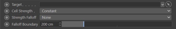
Target
Drag the object to be used as the target into this field. As soon as you do, you will see the vectors change to point to the object, and if you move it around the vectors re-orientate to point to it. The object can be anything, a null object is fine, and once you have arranged the vectors to your liking you can delete the object. Or you can leave it in place and animate its position and the vectors will constantly re-orientate themselves.
Cell Strength
Target mode offers several ways to alter the strength of the effect applied by each vector. The main 'Strength' setting will affect all cells in the object in the same way, but you can vary the individual cell strength with this drop-down menu. The options are:
Constant
The cell strength is at maximum in all cases, regardless of distance from the target object.
By Distance
With this option, the maximum distance of any cell from the target object is calculated and then each cell is assigned an individual strength value depending on how far the cell (note, not the particle) is from the target. The closest cells to the target then have the greatest strength while those which are farthest away have the weakest.
The value obtained for each cell is then adjusted by multiplying by the 'Strength Falloff' and then again by the 'Strength' setting to give the final result.
Strength Falloff
With this drop-down the strength of each vector can be altered depending on how far the particle (not the cell in this case) is from the target. Note that the falloff does not affect the vector direction - they still point towards the target - but to what degree the particles are moved by the vector along that direction. There are four options:
None
The strength of effect is not altered by the particle distance from the target.
Boundary
In this case the effect strength is zero if the particle is outside the boundary (as determined by the 'Falloff Boundary' setting) and at maximum if it is inside the boundary. Note that a strength of zero will mean that the particle direction will not be affected by the vector at all.
Linear
The strength of effect varies linearly with the distance of the particle to the object, being zero outside the boundary and at maximum when the particle is at the target position.
Inverse Square
This is the same as 'Linear' except that the strength decreases by the square of the distance. This causes a very rapid falloff and leads to little or no effect until the particle is very close to the target.
Falloff Boundary
This is the boundary of the effect if 'Strength Falloff' is set to anything other than 'None'. It is show as a yellow sphere in the viewport.
Along Spline, To Spline, Surface Tangent and Surface Normal layers
If 'Flow' is set to one of the four modes which use a spline or a polygon object, these options become available:
In 'Surface Tangent' mode you also have these options:

These modes work as follows:
Along Spline
This option requires a spline object. Here the flow vectors will point in a direction which is at a tangent to the nearest point in the spline.
To Spline
This option also requires a spline object but differs from 'Along Spline' in that the vectors point towards the nearest point in the spline.
Surface Tangent
This option requires a polygon object. The vectors point along a tangent to the surface normal.
Surface Normal
This option requires a polygon object. The vectors point in the same direction as the normal of the nearest polygon.
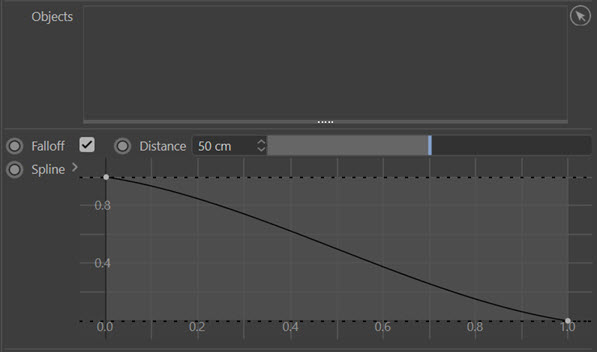
Objects
Drag the splines or polygon objects (depending on the layer type) into this list. You can use multiple objects.
Note: if you use the 'Surface Tangent' or 'Surface Normal' modes and you use a target object with a lot of polygons, each time you change something such as the grid size the vectors have to be recalculated. In these two modes, this will take some time - it may look as if Cinema has frozen but if you wait a few seconds, it will finish updating the vectors. Once the recalculation has been done, the vectors won't need to be updated again unless you change the grid or the target object.
Falloff
If checked, the falloff 'Distance' and 'Spline' settings become available. If it unchecked the falloff spline has no effect.
Note that this is a separate falloff to the main Falloff tab in the object. The Falloff tab is a conventional Cinema 4D falloff which works in the same way as in any other object.
Distance
Grid cells which are further away than this distance from the object(s) have a strength value derived from the right-hand end of the spline. In the screenshot above, this would give them a strength of zero. The closer the cell is to the object, the more the strength value is shifted to the left of the spline, so again, in the above screenshot, the maximum strength would be in cells which were at zero distance from the object.
Spline
The spline used to derive the cell strength depending on how far a cell is from the object.
Direction
Only available in 'Surface Tangent' mode. This is a drop-down menu which controls direction of the vectors.
The menu has these options:
Polygon
The vectors are derived from the surface normal of the polygon nearest the cell. They will be tangential to the normal in 'Surface Tangent' mode but point towards the polygon in 'Surface Normal' mode.
Local X, Local Y, and Local Z
The vectors are derived from the surface normal and a vector pointing along the respective axis of the Flow Field object. This has the effect of pointing the vector along that axis while remaining tangential to the surface ('Surface Tangent' mode) or towards it ('Surface Normal' mode). In these modes, rotating the Flow Field object will not affect the direction of the vectors.
World X, World Y, and World Z
As for 'Local X, Local Y and Local Z' but rotating the Flow Field object itself will affect the tangent direction.
Object
In this mode, you can add a separate object to the 'Object' field and the tangents are then derived from the surface normal and the position of this object. This mode behaves like 'Local X, Local Y and Local Z' but the vectors are aligned to point to the object.
Origin
Each vector is derived from the surface normal and the position of the cell the vector is in.
Object
The object to use when 'Direction' is set to 'Object'.
Particles or ExplosiaFX layers
Particles
In this mode he flow field will track the movement of a stream of particles through it, and for each cell, the vector will be altered to point towards the nearest particle.
ExplosiaFX
This mode will display the vectors generated by ExplosiaFX object(s).
With these modes the same settings as for one of the four spline or polygon object modes are used, but with these additional options.
For 'Particles' mode:

The flow field will then track the movement of a stream of particles through it, and for each cell, the vector will be altered to point towards the nearest particle.
In this case, you should add one or more emitters to the 'Objects' list, rather than polygon or spline objects.
For 'ExplosiaFX' mode:

The flow field will display the vectors generated by an ExplosiaFX object.
In this case, you should add one or more ExplosiaFX objects to the 'Objects' list, rather than polygon or spline objects.
Type
This drop-down menu controls how the flow field vectors are influenced by the particles. It has two options:
Direction
The flow field will depend on the particle direction but its strength is not affected by particle speed.
Velocity
The flow field will depend on the particle direction and its strength is affected by particle speed.
Smoothing
This setting is used to smooth out abrupt changes in vector direction as the particle move in the flow field.
Turbulence or Curl layers
These layers are similar to the modes of the same name in the Turbulence modifier.
With either of these modes, two settings are available:

Scale
Increases or decreases the scale of the turbulence (or curl). Smaller values give less variation between the vectors in adjacent cells, leading to smoother, more flowing (and possibly less interesting) particle movement. Larger values give more variation between cells leading to more chaotic movement. Note that values above 100% may show little change compared to a 100% setting.
Frequency
This affects the rate of change of the vector in each cell. High values give a high rate of change and if too high the particle movement becomes almost random. Low values (e.g. 5%) reduce the rate of change but can give some very interesting results.
Import layer
In the previous version of the FlowField, there was a separate set of controls to load vectors in the form of an .FGA file. This has been greatly simplified and now it is done by creating an 'Import' layer. There is only one setting:

FGA File
Use this field to select an .FGA file. The file will be loaded automatically and the vectors created from it.
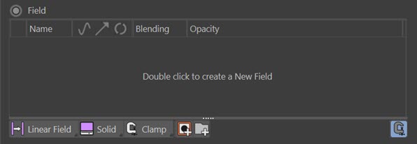
Fields layer
In Cinema 4D R20 and higher you can use Fields to generate the vectors. The options available are the standard interface for creating and editing a Field object:
Surface Flow layer
With this layer the vectors will cause particles will flow over and around an object. The settings are:
Objects
Drag the objects you want to use into this layer. These must be polygon objects, or primitive objects which if made editable would be a polygon object.
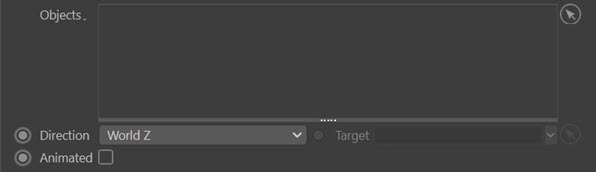
Direction
This is the direction of the vectors. The options are:
Local X, Local Y, Local Z
The vectors are oriented along the selected axis of the FlowField object. Moving/rotating the FlowField object will cause the vectors to retain the same orientation to the FlowField object.
World X, World Y, World Z
The vectors are oriented along the selected axis of the 3D world. Moving/rotating the FlowField object will cause the vectors to change their orientation in respect to the FlowField object.
Object
The vectors point towards an object, which you specify in the 'Target' field.
Target
Only available if 'Direction' is set to 'Object'. Drag the object the vectors should point towards into this field.
Animated
If the object in the 'Objects' list is not animated, or if it is animated and this switch is unchecked, only the object shape is used in generating the vectors. If it is animated and this switch is checked, the velocity of the object is used in calculating the vectors, in addition to the object shape.
Actions quicktab
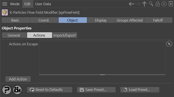
When a particle leaves a Flow Field box, the object will trigger any actions in the 'Actions on Escape' list. You can use this to kill particles which leave the box, for example.
Important: as with all other particle modifiers, the Flow Field will only have an effect on the particle if the particle is within the falloff zone. Therefore, if you set the falloff to anything other than 'Infinite', the action will not be triggered unless the particle is within the falloff when it leaves the Flow Field box.
Actions on Escape
Drag any actions to be triggered on leaving the box into this list.
Add Action
Click this button to create a new action and add it to the list.
Export quicktab
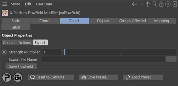
These controls allow you to export a flow field as an .FGA (Fluid Grid ASCII) file. This can then be imported into the Unreal Engine game development system. You can also import .FGA files created elsewhere into the Flow Field object using an Import layer.
Note that due to the different coordinate system used in Unreal, the vectors are rotated to conform with the Unreal system on export. You can reload the .FGA file into the Flow Field, and the vector rotation will be reversed on import.
Please remember that this feature only exports a single .FGA file which is a snapshot of the vectors as they are when exported. If you are using an animated object or shader, which will change the vectors as the scene plays, you will not retain the animation on export; only the current state of the vectors is exported.
Exporting a Flow Field
Strength Multiplier
This setting will multiply the magnitude of the vectors which gives particles their initial speed when the flow field is used in Unreal. By default it is set to 1, which leaves the vectors unchanged.
Export File Name
This is the file to which the flow field will be exported. Select a file in the usual way; if the file doesn't exist, it will be created. When you select an existing file you will be asked to confirm that you want to overwrite it.
The file will not actually be exported until you click the 'Save Flow Field' button.
The file name will stay in this field so that you can make changes to the flow field and re-export it as many times as you like.
Save Flow Field
Click this button to save the flow field to the specified file.
Display tab
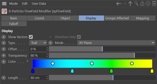
These settings affect how the vectors are shown in the viewport. They are not shown at render time and have no effect on the functionality of the object.
Show Vectors
If this switch is unchecked the vectors will not be shown in the viewport.
Direction Only
When checked, the vector display will show vectors which are all the same size. In this case vector strength is shown by the colour from the 'Color' parameter. If this is unchecked, the size of the vectors will be dependent on the strength of the vector.
This setting is only available if 'Type' is set to 'Line' or 'Arrow'.
Type
The shape used for the vectors. There are four choices: lines, dots or arrows plus a special 'Trail' mode (the default setting).
In 'Trail' mode a trail (which is not an X-Particles trail as in the Trail object) is drawn to show changes in each voxel over time. This can produce some very cool displays!
Mode
With this menu you can alter how the vectors are shown. The options are:
Voxels
A vector is shown for each voxel. This is the same as the display in previous versions of the FlowField object.
XY Plane, YZ Plane, XZ Plane
A single column or row of vectors is shown in the centre of the object. These options give more clarity than a full voxel display, especially with high resolution grids.
Transparency
Use this control to alter the opacity of the vectors. This is useful if the vectors are obscuring other details.
Color
This gradient is used to colour the vectors according to their strength. The weakest vectors use the colour from the left-hand end of the gradient, while the strongest ones use the colour from the right-hand end.
If all vectors have the same strength then the colour from the right-hand end of the gradient is used.
Length
Only used when 'Type' is set to 'Trail'. It is the length of the trail shown in the display.