Surface Scatter Object
 The Surface Scatter object enables you to scatter objects over another object using features such as texture, shaders, illumination, and topology to determine where the objects are placed.
How it works
The Surface Scatter object encapsulates an X-Particles emitter and a Generator object to generate and scatter objects. Everything it does you can already do with the emitter and generator but Surface Scatter provides a quick and easy way to set up scattering without having to set numerous options in the emitter and generator.
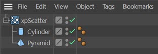
The objects to scatter must be made child objects of the Surface Scatter object like so:
Interface
This object has the following sections:
For the buttons at the bottom of the interface, please see the 'Common interface elements' page.
Parameters
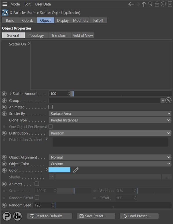
Object tab
General quicktab
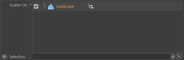
Scatter On
The surfaces to be scattered with other objects. This can be be any polygon object or a parametric object which, if made editable, would be a polygon object. Splines are also supported.
If you uncheck the checkbox next to the object name, nothing will be scattered onto that object until it is checked again.
Selection
This field is only visible if an object is present and selected in the 'Scatter On' list:
You can drag a selection tag from the surface object into this link field, and the objects will only be scattered onto the selected area. The selection can be polygons, points, edges, or a vertex map; internally, it will be converted into a polygon selection before use. Note that depending on the object some non-polygon selections may result in an empty polygon selection on conversion.
Scatter Amount
The number of objects to scatter on the surface. If you click the little arrow next to the label, you see this setting:

Render Count
This is the number of objects that will be generated when rendering to the picture viewer (NOT when rendering to the viewport). By default it is set to zero, which will generate the same number of objects as in 'Scatter Amount'. Any non-zero value will result in that number of objects being generated on rendering to the picture viewer.
Group
You can drag a particle group into this field and the Surface Scatter object will use the parameters such as colour and scale from this group.
Note that if you subsequently change a setting in the group, such as colour or scale, you may need to force the Surface Scatter object to redraw the scene to show the changes. Simply hit the 'A' key on the keyboard to do this, or switch to a different tab in the Surface Scatter object's interface.
When using a group, remember to set the speed in the group to zero. If you don't, the objects will be offset from the surface by the distance a particle would travel in one frame!
Scatter By
This is the primary method to determine how the objects are scattered over the surface. The options are:
Polygons
Objects are scattered over the polygons of the 'Scatter On' objects. The polygons are not weighted by size - that is, all polygons have an equal chance of receiving scattered objects.
Surface Area
This is the same as for polygons, but account is taken of the relative sizes of the polygons, so larger polygons receive more scattered objects. This can result in a more even distribution of objects.
Surface Texture
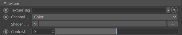
With this option the area to be covered is controlled by a texture or shader. If you select this option, these parameters become available:
The settings here are a subset of those available in the emitter if you control emission by texture, For convenience the descriptions are reproduced here:
Texture Tag
You can drag a texture tag into this field and the emitter within the Surface Scatter object will use the material referenced by that tag. Any of the texture tags assigned to the surface object may be used.
Any projection mapping can be used in the tag except Frontal or Camera mapping.
Using a tag is convenient if you have already set up a material and don't want to have to duplicate it in another shader. Once you add the tag to this field, you can select the channel to sample in the 'Channel' drop-down menu, but you can no longer use the 'Shader' field - that is, you can't use a texture tag and a shader simultaneously.
Channel
This is the material channel which governs the generation of the objects to be scattered.
If you have dragged a texture tag into the 'Texture Tag' field, you can choose the channel to use from the material. By default this is the Color channel, but you can choose from several others. One thing you can do is use a channel which is not being used in the material. For example, you could set up a shader to govern object placing in the displacement channel but leave that turned off in the material editor. The emitter can still sample that channel even though it is not being used in the material.
Shader
Instead of using an existing texture tag, you can set up any shader in exactly the same way as if you were using the material editor. Or, you can copy a channel from a material and paste it into this field. Note that the 'Shader' field is disabled if there is a texture tag in the 'Texture Tag' field. If you set up a shader, then add a texture tag, only the tag is used; the shader will be ignored.
Contrast
The scattering of objects is controlled by the overall colour brightness of the sampled texture or shader; the brighter the colour, the more objects are generated. If you find that more objects are being scattered in darker areas than you would like, you can increase the 'Contrast' setting to reduce the number in dark areas. Conversely, turning down the contrast below zero will increase the number of objects in darker areas.
Surface Illumination
With this option the area to be covered is controlled by the light shining on the surface. If you select this option, these parameters become available:
The settings here are a subset of those available in the emitter if you control emission by illumination, For convenience the descriptions are reproduced here:
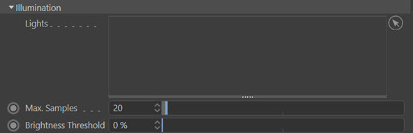
Lights
Drag the lights you want to control object scattering into this list. If there are no lights in the list, no objects will be scattered on the surface.
Max. Samples
If you use a spotlight, the emitter will sample the surface of the object in an attempt to find an area which is illuminated. If the spot is very small, this may take a long time, so this setting controls how many samples are taken before the emitter assumes that the object is not illuminated. Increase this value if you use a small spot and don't get many objects being scattered.
Brightness Threshold
The angle of incidence of the light rays striking the object surface is compared to this setting. The threshold value must be exceeded for any objects to be generated, so the higher this setting, the fewer objects are scattered. If the light rays strike the surface at just under a right angle to the normal, you will need to set this value very low as otherwise it is likely that no objects will be generated. But if the light rays are almost parallel to the surface normal, this setting will have no effect unless set very high.
Polygon Centre
Objects are scattered on the centre of polygons. With this setting, the switch 'One Object Per Element' becomes available, and if that is checked, one object will be generated at the centre of each polygon.
Vertices
Objects are scattered on the vertices of the 'Scatter On' objects. With this setting, the switch 'One Object Per Element' becomes available, and if that is checked, one object will be generated at each vertex.
Edges
Objects are scattered on polygon edges.
Object Volume
Objects are generated inside the 'Scatter On' objects. The best results are obtained using objects with closed volumes such as a sphere, pyramid, etc.
Clone Type
This menu lets you choose how the clones of the objects to be scattered are generated. 'Duplicate' generates full copies, as if you duplicated the object in the object manager. 'Instances' generates Cinema 4D instances, while 'Render Instances' generates, well, render instances. Details of instances and render instances can be found in the Cinema 4D documentation.
One Object Per Element
This setting is only available if 'Scatter By' is set to 'Polygon Centre' or 'Vertices'. If checked, one object will be generated at the centre of each polygon (or at each vertex).
Distribution
Suppose you have two or more more objects to be scattered. What should the relative proportion of these objects be?
This menu has two options:
Random
The objects to be scattered are chosen randomly. In practice, this results in an equal distribution of the various objects.
By Gradient
With this option, you use a gradient to determine the relative proportion of the objects. This is the 'Distribution Gradient'.
Distribution Gradient
This gradient is only available if you set 'Distribution' to 'By Gradient'
Using this gradient is not difficult but the first thing to remember is that the colours are completely irrelevant - you can use any colours you like, it makes no difference. The critical thing is the position of the gradient knots.
Example 1
In this example there are two objects to be scattered equally, and the gradient therefore needs one knot, which will be located at position 50%:

The space represented by the red line is 50% of the gradient, as is that represented by the green line, so both objects are distributed equally. If the knot was at 15%, about 15% of the scattered objects would be the first object and the second object would account for the remaining 85% of the scattered objects.
Example 2
Here we have three objects to be scattered so we need two knots which in this example are at 25% and 75%:

So, 25% of the objects (the red line) would be object 1, 50% (green line) would be object 2, and 25% (yellow line) would be object 3. By moving the knots you can easily alter the relative numbers of each object.
Object Alignment
This is the alignment of the scattered objects along a particular axis. Much of the time, you will want the alignment to be along the normal of the surface where the object is generated, so this is the default setting. But that won't always be the case. Trees, for example, might be expected to grow straight up even if the surface on which they stand is not horizontal.
With this menu, you can select the direction in which the object is aligned. This can be the X, Y, or Z axis, either in the positive or negative direction, the surface normal, phong normal, or be entirely random.
Object Color
You can set the colour of the scattered objects with this menu. This only applies if the scattered objects do not have a material applied to them; if they do, the material takes precedence. The options are:
None
No colour is set.
Shader
The colour is obtained from a shader in the 'Shader' link field.
Source
The colour of the generated objects is the source object's base colour. For example here, where the cylinder is green and the pyramid red:
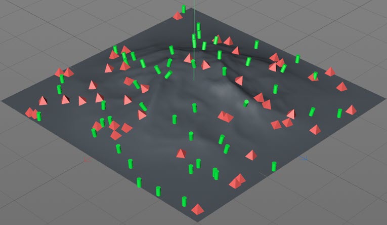
Custom
The colour is obtained from the 'Color' field.
Color
The colour of the generated objects when 'Object Color' is set to 'Custom'.
Shader
The colour of the generated objects when 'Object Color' is set to 'Shader'. Add a shader of your choice to this field.
Animate
This and the following two parameters are identical to those found in the Generator object. For convenience, the description is reproduced here.
Suppose you are generating a sphere whose radius is keyframed to increase from 0 to 100 over a number of frames. If 'Animate' is checked, when a new sphere is generated its initial radius will be 0 and will increase to 100 as the particle gets older. If 'Animate' is off, then for a new sphere generated at (for example) frame 30, it will have the radius of the original sphere at 30 frames. Normally you would leave this switch on but it can be turned off if desired.
Note: for this to work the object must be animated using PLA animation. Using deformers or expressions such as the Pose Morph tag will not work. This is a limitation of Cinema 4D itself, not of X-Particles.
Scale and Variation
The Scale value determines how fast the object will be animated. For example, if you have an animated bird flapping its wings, a scale of 200% will cause the wings to flap twice as fast as normal. If you add some variation, the objects will be animated at different speeds.
Random Offset and Offset
By default, all animated objects will be animated from the same point in the scene. What this means is that all objects will appear to have the same animation - so birds will all flap their wings in unison, for example. That might be what you want, and if so, you can adjust the starting point by altering the 'Offset' value. Often, however, you will want the objects to be animated from different starting points from each other, which gives a more natural effect. To do this, check the 'Random Offset' switch.
Random Seed
A random seed value used to select objects and their position on the surface.
Topology quicktab
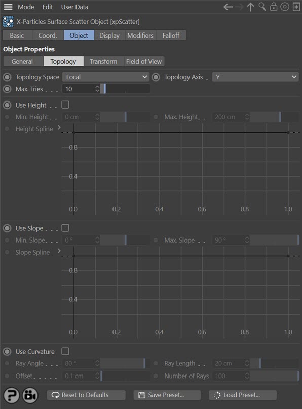
These parameters are identical to those of the same name in the emitter. For convenience their descriptions are reproduced here.
Topology Space
This drop-down menu has two options:
Local
The position of the generated object is relative to the surface object (to be precise, to its axis). This means that moving or rotating the object will not affect the height or slope of any polygon, since they remain the same relative to the axis.
World
With this option the height and slope of any polygon is relative to the 3D world axis. Moving or rotating the surface object may then have a significant effect on the polygons used for scattering objects.
Note that the space is not relevant to the curvature as this is always calculated in local space.
Topology Axis
The height and slope are assessed relative to either the X, Y, or Z axes. By default this is the Y axis.
Note that the axis is not relevant to the curvature.
Max. Tries
Depending on the object and other factors, it may be very difficult or impossible to find a suitable point to add an object. To prevent Cinema 4D from hanging due to a calculation that never ends, Surface Scatter will only try to find a suitable point for the number of times given in this setting. If you find that the number of objects being scattered is very small, you can increase this value but this will of course slow down the process.
Use Height
Check this switch to enable height control of object scattering.
Min. Height, Max. Height
The point where an object is generated must fall within the height range given by these two settings. No objects will be generated on points outside of this range. Remember that these settings are relative to the object axis when 'Topology Space' is set to 'Local' but to the world axis when it is set to 'World'.
Height Spline
By default the use of height-based control will result in a hard boundary between the area where objects are scattered and those where they are not. You can use this spline to feather the edges of the scatter area, or use it to control the pattern of objects within the area (e.g. you could change the spline to give stripes where objects are placed alternating with stripes of no objects).
Use Slope
Check this switch to enable slope control of object scattering.
Min. Slope, Max. Slope
The point where an object is generated must fall within the slope range given by these two settings. No objects will be generated on points outside of this range. Remember that these settings are relative to the object axis when 'Topology Space' is set to 'Local' but to the world axis when it is set to 'World'.
Note that the minimum slope is zero degrees. This occurs when the normal of the polygon used for scattering is parallel to the selected axis. The maximum slope is either +90 or -90 degrees and these are reached when the polygon normal is at right angles to the selected axis. Not all objects can have negative slopes. A sphere does - these are the polygons on the 'underside' of the sphere. But a Landscape object does not - all its polygons have a slope of zero degrees or greater.
Slope Spline
This is identical to the spline used for height-based scattering, but for the slope instead.
Curvature
Check this switch to control scattering from the curvature in an object.
What is curvature? It is the folds and other areas where polygons are closely adjacent to others and at an angle to one another. It is the same principle as ambient occlusion, but in this case objects accumulate in the 'shadowed' area. Not all objects have such things. If you try to scatter objects in the crevices on a sphere, no objects will be generated as it has no crevices. Curvature can also apply to ridges in the object, rather than folds.
The way this works is that the emitter will select an emission point for a particle. 'Rays' are then emitted from that point, and if they hit another polygon at a suitable angle from the one containing the emission point, within the specified range, a particle is emitted.
Ray Angle
The polygon hit by a ray must be at an angle to the source polygon by less than this value. For most purposes the default value of 80 degrees will be fine. If you reduce it, you will see fewer objects generated and playback will take longer, but on curved surfaces the object placement may be more restricted to the curvature.
Ray Length
The distance between the point the ray hits and the source point must be less than this value for objects to be generated. If you make this too large, objects may be placed on polygons some distance away and which do not even form a curved area with the source polygon.
Offset
If the ray source point is the same as the emission point generated by the emitter, it will register an immediate hit on itself. This is not useful so the ray source point is offset by this value along the surface normal. You can almost always leave this at the default, but if you have a very small model or one where polygons are extremely close together, you might need to reduce it.
Number of Rays
This is the number of rays emitted from the generated source point in order to find another polygon nearby. The default of 100 should be fine in almost all cases. If you find the playback is slow you can reduce this value at the expense of accuracy (some adjacent polygons may be missed and a particle therefore not emitted).
Note: for curvature emission to work the surface object must be a single mesh. If you have a mesh with multiple separate parts (and the Cinema 4D Figure primitive is built like this) you can add the mesh hierarchy as the child of a Connect object and use that as the surface object.
Transform quicktab
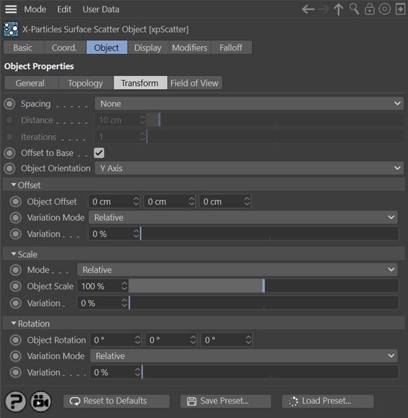
Spacing
When objects are scattered, it is quite likely that some or many will overlap. You can avoid this by using this menu. The options are:
None
Do nothing and accept overlapping objects.
Kill
Kill all objects which are within the distance of one another given in the 'Distance' setting. This can result in a marked reduction in the number of generated objects, but is very fast.
Push
Instead of killing objects which are too close together, this option will try to push them apart. Surface Scatter will try to separate objects which are closer than the 'Distance' setting.
The problem with this option is that pushing two objects apart may bring them closer to other objects. For this reason, one iteration is not always sufficient. By increasing the value in 'Iterations' the push apart algorithm is executed more than once and gives a more accurate result. However, with a large number of objects this can be very slow.
Distance
If two objects are closer together than this distance, they will either be killed or pushed apart, depending on the 'Spacing' setting.
Iterations
The number of iterations to use if 'Spacing' is set to 'Push'.
Offset to Base
Ideally, the objects to be scattered will have their axis located at the point which you want to be touching the surface. A tree, for example, would probably have its axis located at the bottom of the trunk where the roots start, so that when placed on the surface the tree doesn't float above the surface and isn't buried in it.
However, this isn't always possible - for example, a parametric object such as the Cylinder primitive will always have the axis halfway along its length and that cannot be altered unless it is made editable.
In some cases you can overcome this by checking this switch. The Surface Scatter object then assumes that the axis is located halfway along one of the object's axes and adjusts its position on the surface so that its base rests on the surface. This works well with symmetrical objects where the axis is located in the object centre but with other objects with an offset axis, it won't work, or won't work very well. In those cases the only option is to adjust the axis position within the object or use some other method such as making the object the child of a null object and adjusting the position of the null relative to the child so that the null's axis is at the required position.
Note that the axis could be located halfway along any axis, so it becomes crucial to choose the correct axis to use. This is where the 'Object Orientation' parameter comes in.
Object Orientation
Remember that the essential working of this object is the emission of particles from a surface, with an object being generated in association with each of those particles.
In earlier versions of X-Particles the particle's direction used the particle Z-axis, which was always oriented along its initial direction of travel. This meant that the generated object's Z-axis would be aligned along the particle's direction. But this isn't always desirable. Imagine a tree whose Y-axis is along the height of the tree. If the tree is generated with its Z-axis aligned along the particle direction, and the particle direction is along the Y axis, the tree will actually lie on its side.
An example may make this clearer. In this image a primitive Cylinder, whose height is aligned by default along the Y axis, is scattered over a plane object. This is the result:
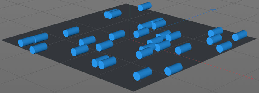
This happens because the cylinder height is along the Y axis but the particle Z-axis, and therefore the object's Z-axis, is pointing upwards, since that is the particle direction. We can't change the direction if that is set to the surface normal, but we can change the particle - and therefore the object - orientation. If we change this setting to the Y axis, we see this:
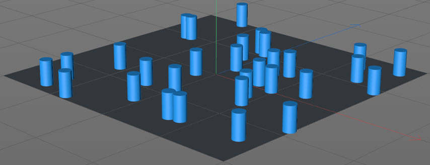
Nothing has changed other than the orientation of the particle, which is carried through to the object. The direction of the particle is still the same, but now its Y-axis is oriented along the direction, so the object's Y-axis also points along the direction. Whether or not you need to change this menu depends on which axis you want the object to point away from the surface along.
Offset settings
You can use the parameters in this section to offset the object position from its initial value when generated.
The Offset section looks like this by default:
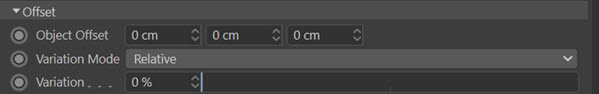
Object Offset
The scattered objects are given an initial position on the surface but this can be changed with these values. Negative values are possible.
Note that any value you specify here is in addition to, not instead of, the position the object is given when it is generated.
Variation Mode
If you want to add some variation to the offset values you have input, you can do it in one of two ways:
Relative
In this mode the variation is set as a percentage of the added offset, so 0% represents no variation. This is simple to use but this mode adds variation equally to all three axes. If you want to vary the offset along an individual axis, select 'Absolute' mode instead.
Absolute
If you select this mode the interface changes slightly:
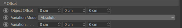
Now the variation is in absolute values and can vary along different axes.
Variation
This enables you add variation to the added offset. It is either a percentage value (in 'Relative' mode) or actual values in scene units ('Absolute' mode).
Scale settings
You can use the parameters in this section to alter the object size.
The Scale section looks like this by default:
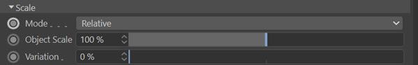
Mode
By default objects are generated at the same size they have when added to the Surface Scatter object. Of course, you might want to make them smaller or larger, which you can do in one of two ways.
Relative
In this mode the scale is set as a percentage of the initial size, so 100% is the same as that size. This is simple to use and you can add variation to the size of the objects with the 'Variation' slider. But this mode scales the object equally along all three axes. If you want to scale the object along an individual axis, select 'Absolute' mode instead.
Absolute
If you select this mode the interface changes slightly:
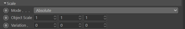
In this mode you can change the scale differently along individual axes. You can also add variation differently along different axes. This is the most flexible mode but requires more input from you.
Object Scale
A percentage of the initial scale (in 'Relative' mode) or actual scale values (in 'Absolute' mode).
Variation
This enables you to vary the size of the scattered objects. It appears either as a percentage slider or as a vector input depending on the selected mode.
Rotation settings
You can use the parameters in this section to rotate the scattered objects.
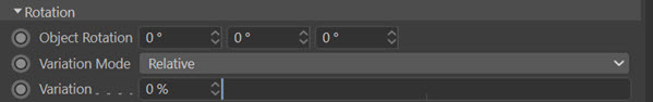
The Rotation section looks like this by default:
Object Rotation
By default objects are rotated to match the particle orientation and direction. If you need to add additional rotation you can do so in this field.
Note that any rotation you specify here is in addition to, not instead of, whatever rotation the object is given when it is generated.
This field is a vector representing HPB (heading, pitch, bank) rotation.
One way you might want to use this is to add some rotation to something like a tree. If you have lots of trees on a surface they are going to look identical and rather odd, but if you add some random rotation they will look much better. To do this, set a value in this field, then add some variation to it with the 'Variation' field.
An issue you will run into concerns the axis to rotate around. For example, suppose a tree has its height along the Y axis and you have therefore correctly selected the Y axis in 'Object Orientation' (see above). Now you want to rotate the tree around its own Y axis. Which value should you change - H, P, or B? In this example you would choose the H value in this field (the first one) but if you selected one of the other axes in 'Object Orientation' you would need to use the P or B values instead. A little trial and error will soon show which value to use. Incidentally, there's nothing to stop you adding additional rotation around the other axes as well, if you want to.
Variation Mode
If you want to add some variation to the rotation values you have input, you can do it in one of two ways:
Relative
In this mode the variation is set as a percentage of the added rotation, so 0% represents no variation. This is simple to use but this mode adds variation equally to all three axes. If you want to vary the rotation along an individual axis, select 'Absolute' mode instead.
Absolute
If you select this mode the interface changes slightly:
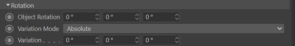
Now the variation is in absolute values and can vary along different axes.
Variation
This enables you add variation to the added rotation. It is either a percentage value (in 'Relative' mode) or actual values in degrees ('Absolute' mode).
Field of View quicktab
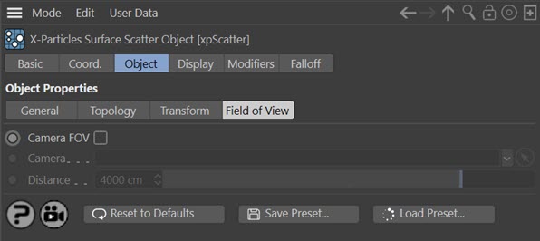
Camera FOV
If checked, objects will only be scattered within the field of view of the camera in the 'Camera' link field.
Camera
Drag the camera whose field of view you want to use into this field.
Distance
This is the maximum distance from the camera at which objects will be generated. No object will be generated if they would be further away from the camera than this value.
Display tab
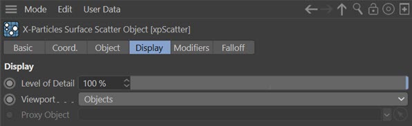
Level of Detail
If you reduce this value, you will see fewer generated objects in the scene, which may speed up the viewport and playback.
Viewport
This menu controls what you see in the viewport. The default is 'Objects', so you see the actual generated objects. The options are:
None
No generated objects are displayed.
Particles
Objects are not displayed but the underlying particles are shown.
Proxy
Instead of the generated objects you can substitute a simple proxy object instead. Drag the object to use into the 'Proxy Object' field. If that is left empty the generated objects are shown.
Cubes
The generated objects are replaced by simple cubes.
Objects
The actual generated objects are shown (this is the default setting).
Proxy Object
Only available if 'Viewport' is set to 'Proxy'. Drag the object to use as a proxy into this link field.
Modifiers tab
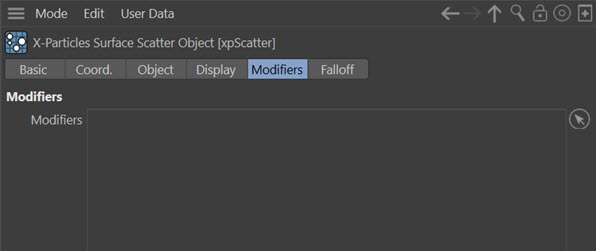
The Surface Scatter object uses an emitter to determine where to place the generated objects. This emitter can be affected by particle modifiers in the same way as any other emitter. However, to prevent other modifiers you add to the scene affecting the emitter internal to the Surface Scatter, the emitter's modifier list is set to Include rather than Exclude (see the emitter modifiers page for more details).
This means that if you want a modifier to affect the inbuilt scatter emitter, you must add it to this list. Typically, the most useful modifiers are likely to be the Scale and Spin modifiers, but in theory you can add any modifier here.
Modifiers
Drag the modifiers you want to affect the scatter particles into this list.
Falloff tab
You can add any Cinema 4D falloff or field object to this tab. Objects will then only be generated within the field of effect of the falloff.