ExplosiaFX: Display
This page contains the reference manual for the Display tab in the ExplosiaFX object. The tab controls which channels you see in the editor. It has no effect on what is rendered.
Interface
The tab interface looks like this:
Important: please note that the new OpenGL display mode in this version of ExplosiaFX is not available in Cinema 4D S22 and higher at the present time.
Parameters
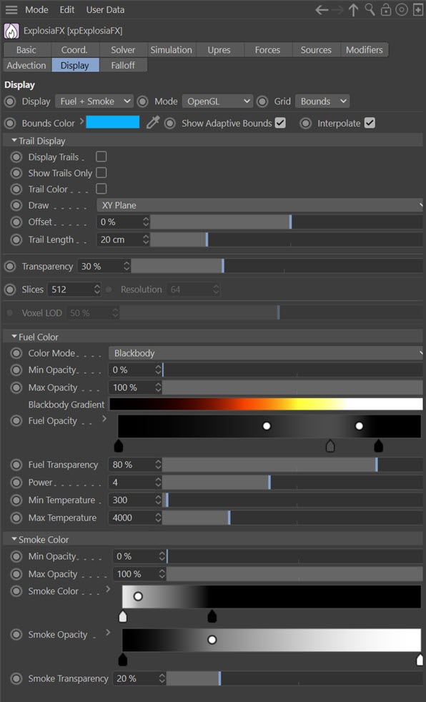
Display
This drop-down menu controls which channels are shown in the editor. Each option apart from 'Color' has a colour gradient and an opacity gradient associated with it for the display. The options are:
Temperature
The voxel temperatures are shown.
Smoke
Displays the smoke channel.
Fuel
Displays the fuel channel.
Fuel and Smoke
Both fuel and smoke are shown. This is the default setting. Note that with this option the gradients for both fuel and smoke are available.
Velocity
In this mode, the actual flow vectors in the voxels are shown. The same gradients are also used for the Speed channel. Note that you can alter the vector display by using the 'Voxel LOD' slider, which is only available for this channel.
Speed
The speed channel is shown. It uses the same gradients as the 'Velocity' channel.
Color
No gradients are available for this channel. To use it, first check 'Color' in the solver settings (Solver tab). Then the colour which is used is determined by the Explosia FX Source tag.
Mode
This is the display mode menu. The options are:
Off
The display is turned off and nothing will be seen if the simulation is run.
Slices
The default setting. The display is composed of a number of slices, and the detail can be adjusted by altering the 'Slices' parameter. The more slices, the more detailed the result, but it will be slower to run.
Grid
In this each voxel is coloured as required, giving rise to a grid of discrete dots rather than a continuous display. This mode is faster than 'Slices' but much less detailed. You can control the level of detail with the 'Voxel LOD' slider.
Centre Slice
One single slice is used from the centre of the source object. A very fast mode but without much detail.
OpenGL
 A new and very realistic viewport display mode.
Please note that unfortunately this mode does not work at present with Cinema 4D S22.
Grid
This menu controls how the solver object is displayed. It has these options:
None
Only the adaptive bounds of the solver are displayed, unless those are also disabled.
Bounds
Only the bounding box of the solver and the adaptive bounds are shown.
Voxels
Each voxel is displayed as a small cube.
Back
A grid showing the voxel size is drawn on the furthest wall of the solver from the camera.
Base
A grid showing the voxel size is drawn on the base of the solver.
Bounds Color
The colour used to draw the adaptive bounds.
Show Adaptive Bounds
Regardless of the selected option in 'Grid'. if this switch is unchecked the adaptive bounds are not drawn.
Interpolate
If checked, colours between neighbouring voxels are interpreted. If unchecked, colours are shown as discrete voxels, giving a blocky appearance. This switch is only available if 'Mode' is set to 'OpenGL'.
Trail Display
With these settings a trail (not an X-Particles trail as in the Trail object!) is drawn to show changes in each voxel over time. This gives you much more information about how temperature or other parameters are changing within the solver. For example, the image below shows three hardware renders at 1 second through a very basic ExplosiaFX simulation. On the left is the centre slice render displaying the fuel channel. In the middle is the trail display, using the colours from the Fuel Color gradient. On the right the switch 'Trail Color' switch has been checked so the colours are obtained from the custom 'Trail Color' gradient:
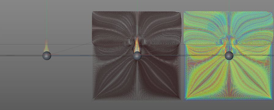
In the two trail displays you can see how the fuel is changing in the rest of the solver, not just in the centre where the actual burning is taking place.
If the display channel was set to temperature or smoke etc., the colours used for the trails would be taken from the colours used for those channels, unless of course the 'Trail Color' switch was checked.
Display Trails
Check this switch to display the trails.
Show Trails Only
If this switch is checked, only the trails are displayed, so the temperature, smoke, etc. displays are not shown.
Trail Color
If this switch is checked, the trail colour is taken form the 'Trail Color' gradient which appears. If it is unchecked the trail color comes from the gradient used to colour the display (that is, the 'Smoke Color' gradient when 'Display' is set to 'Smoke' and so on).
Trail Color
This gradient is only visible when the 'Trail Color' switch is enabled. In that case the trail colours are taken from this gradient.
Draw
This menu determines where the trails are drawn. The options are the three orthographic planes XY, ZY and XZ, plus 'Voxels', where a trail is drawn for each voxel (within the adaptive bounds, if 'Adaptive Bounds' is enabled, or within the entire solver if not).
Offset
By default, if 'Draw' is set to one of the orthographic planes, the trails are drawn in the centre of the adaptive bounds (or the centre of the whole solver if 'Adaptive Bounds' is disabled). You can offset the drawing plane from the centre by using this control.
This has no effect if 'Draw' is set to 'Voxels'.
Trail Length
The length of the trails in scene units.
Transparency
The overall transparency of the display can be altered using this setting.
Slices
The number of slices to take through the simulation if 'Mode' is set to 'Slices' or 'OpenGL'.
Resolution
The resolution of the display. The higher it is, the more detailed the display, but the slower it is to be drawn. If you increase this too much, it will slow the simulation down significantly. Only available if 'Mode' is set to 'Slices' or 'Center Slice'.
Voxel LOD
The level of detail of the voxel display. Only available if 'Display' is set to 'Velocity' or 'Mode' is set to 'Grid'.
Display color sections
Each display type will have its own group of settings but in some cases these are identical in function between different displays.
Min Opacity, Max Opacity
These values control where along the opacity gradient the opacity value is taken from. These settings are available for the temperature, fuel, and smoke displays.
Color and Opacity Gradients
All display types except 'Color' have two gradients, one for colour and one for opacity.
There are separate pairs of gradients for each parameter option in 'Display', apart from 'Velocity' and 'Speed' which share the same gradients, and 'Color', which doesn't have any.
Temperature display settings
In addition to the gradients, the temperature display has the following settings:
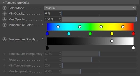
Color Mode
This menu determines whether the colours are controlled by blackbody radiation ('Blackbody') or can be set manually ('Manual').
Note that this menu is only available if the display mode ('Mode' menu) is set to 'OpenGL'. All other displays automatically switch this menu to 'Manual'.
If you choose 'Blackbody' the temperature colour gradient is not available because the colours are derived from the standard blackbody colour spectrum. Additional settings then become available.
Blackbody gradient
The colour gradient used. It cannot be edited directly but will be altered if you change the 'Power', 'Min Temperature' or 'Max Temperature' settings.
Temperature Transparency
Controls the overall transparency of the temperature display.
Power
The power of the blackbody radiation. Reducing this value will shift the blackbody gradient to the left (you can see this gradient updating as you change this value).
Min Temperature, Max Temperature
These values will shift the blackbody gradient to the left or right and alter the temperature display accordingly.
Smoke display settings
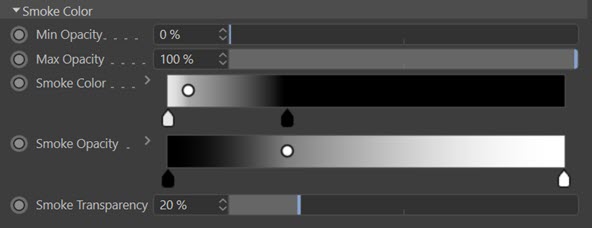
There is only one additional setting here.
Smoke Transparency
This setting controls the overall transparency of the smoke.
Fuel display settings
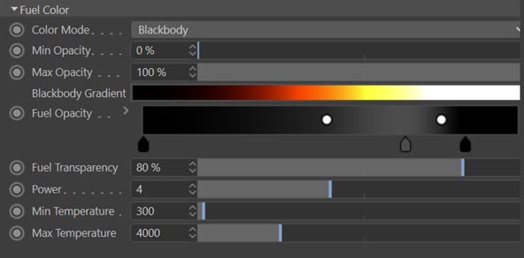
These settings are identical to the temperature display settings above; please refer to that section for details. The only difference is that by default the fuel display mode is set to 'Blackbody'.
Velocity and Speed display settings
These displays share the same settings.
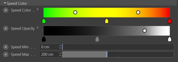
There are two additional settings:
Speed Min, Speed Max
These values determine where on the 'Speed Color' gradient the color is sampled (and the seam for the 'Speed Opacity'). If the voxel speed is at or lower than 'Speed Min', the colour is taken from the left-hand end of the gradient; if it is at or higher than 'Speed Max', it is taken from the right-hand end.