The Sound Shader
The Sound Shader is a shader which can be used in a Cinema 4D material to colour an object by means of a sound file. It does not require an X-Particles emitter or other object to work, but materials with a sound shader can, of course, be applied to the X-Particles Generator, Sprite, Skinner, etc.
Interface
This is the shader's interface:
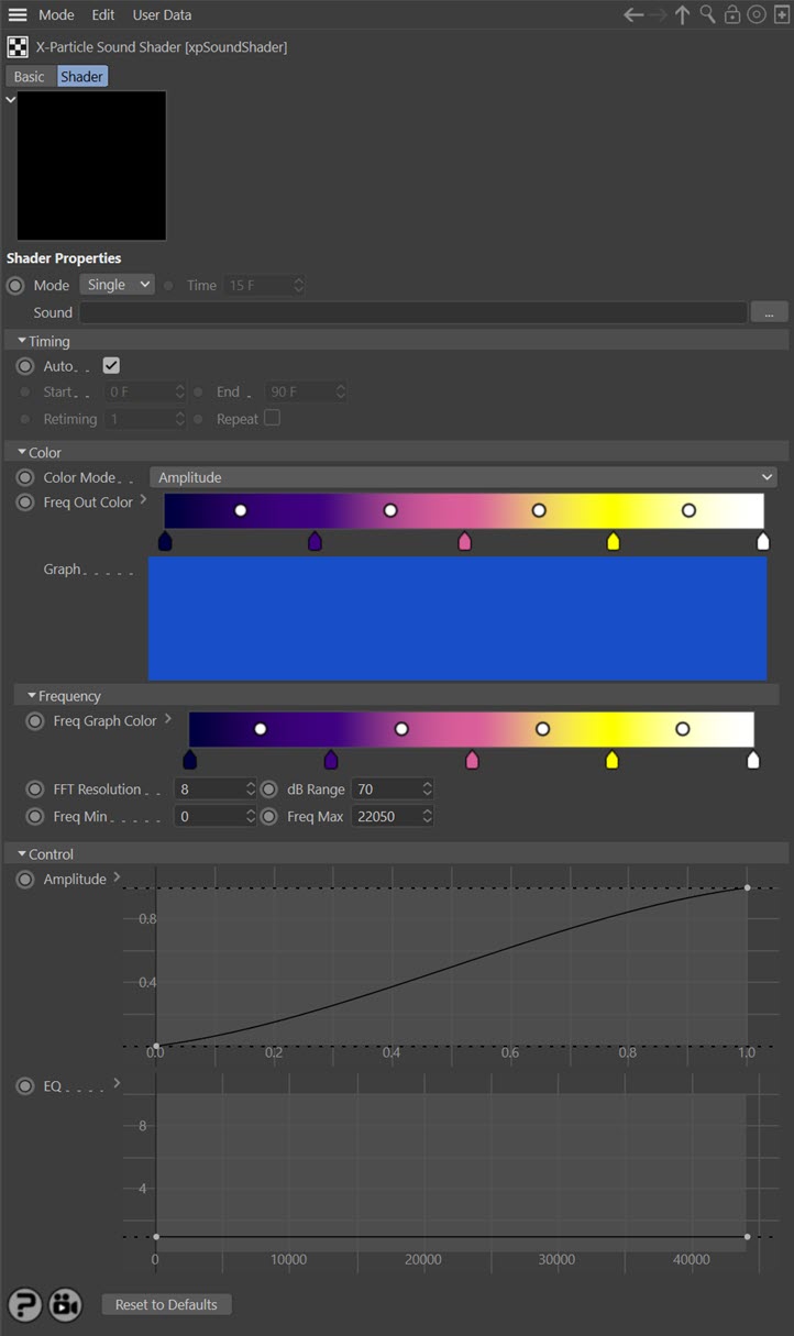
For the buttons at the bottom of the interface, please see the 'Common interface elements' page.
Using the Sound shader
Using the shader is very simple. Add it to the channel you want to use in a Cinema 4D material, then adjust the settings as required. You will need a sound file in .wav format but no other X-Particle components are required.
As with the Sound modifier, the shader carries out a Fast Fourier Transform (FFT) on the sound file and the settings in the shader are applies after the FFT has taken place. For more details please see the Frequency section below.
Note: this shader doesn't actually play the sound file! This is due to the way Cinema 4D implements sound playback. To play the sound you must add a sound track to the timeline window; full details are contained in the C4D reference documentation.
Settings
Mode
Single
The object is shaded with a single colour.
Line
This mode takes a single slice of the sound at the current time and shades the object in the U direction according to the the frequencies in the sound file.
Grid
This is the same as 'Line' but shades the object in the V direction over time. The time can be specified in the 'Time' setting.
Time
The time to use when 'Mode' is set to 'Time'.
Sound
The sound file to use. Click the button with three dots to load a sound file, which must be in .wav format.
Timing section
This section controls the mapping of the sound file time onto the particles.
Note: the controls in this section do NOT affect the actual audio playing of the sound file. Remember that this shader does not generate an audible sound, Cinema controls this separately. If you want the sound to loop in the same way as the shader, you will have to set this up manually.
Auto
If this switch is checked, the shader uses the sound in time with the scene timeline. 'Auto' must be unchecked for the following settings to become available.
Start, End
These are time values which control when on the scene timeline the audio is mapped to the particles. For example, if 'Start' is zero and 'End' is three seconds, the audio file will play for three seconds and then stop. (This is influenced by the 'Retiming' value, see below.)
Retiming
This enables the audio's timing to be changed. For example, suppose 'Start' is zero and 'End' is three seconds. With 'Retiming' at the default value of 1, the audio file will play for three seconds and then stop. You can see that the cyan bar in the graph stops at a specific point. If 'Retiming' is increased to 2, the audio file will still only play for three seconds, but it will play twice as fast, as you can see from the position of the cyan bar.
Repeat
Checking this switch will loop the sound file. So if you have set the 'Start' to zero and the 'End' to three seconds, the sound file will run for three seconds then loop back to the beginning.
Color section
Color Mode
The shaded colours can be derived from either the sound amplitude or frequency in the sound file after the FFT has been applied. There are two options, and you will see the 'Graph' display change accordingly:
Amplitude
The amplitude distribution is used.
Frequency
The frequency distribution is used.
Freq Out Color
This is the color gradient used for the output of the shader. The colour used depends on the intensity (amplitude) of each frequency, low amplitudes using the colour on the left of the gradient and high amplitudes the colours to the right. Changing these colours only affects the final output; the colours in the graph will not change (use the 'Freq Graph Color' gradient for this).
Graph
The graph is a representation of the complete sound file. It is a graph of amplitude or frequency intensity (on the vertical or Y axis) over time (on the horizontal or X axis). The frequency ranges from the minimum frequency at the bottom (i.e. bass frequencies) to the maximum frequency at the top. This range (minimum to maximum) can be changed by adjusting the 'Freq Min' and 'Freq Max' settings (see below).
The cyan vertical line on the graph is the current time in the sound file.
Frequency section
This section controls how the frequencies in the sound are analysed. It uses a process called Fast Fourier Transform (FFT) to do this; this is a complex subject but you don't need to know how it works to use this shader! If you are interested much more detail can be found on the net, for example see https://en.wikipedia.org/wiki/Fast_Fourier_transform
Freq Graph Color
These are the colours to use in the 'Graph' display only. The gradient does not affect the final output of the shader, which is controlled by the 'Freq Out Color' gradient, so you can change this gradient to anything you like without affecting the output.
FFT Resolution
This controls how many discrete chunks (FFT bins) the frequency range is split into. Lower values give a coarser result. For example, the main screenshot shows the graph with an FFT resolution of 8. If that is reduced to 3, this is the result:

You can see that the lower resolution has resulted in a much smaller number of FFT bins. This will affect the degree of control the shader can exert over the particles.
Be careful when increasing this value. If you increase it too much the time taken for the calculation will increase greatly and it may even appear that Cinema has frozen. If that happens, wait until the calculation finishes and reduce this value.
However, if you have a very narrow frequency range (as determined by the 'Freq Min' and 'Freq Max' settings) you will need to increase the FFT resolution otherwise it will not have sufficient frequency resolution. Note that increasing the frequency resolution reduces the time resolution so you end up with a slower calculation (needs a bigger chunk of the sound) and changes in the audio over time become smeared together.
dB Range
The audio intensity is converted into decibels (dB). Reducing this value will start to remove low-amplitude sound and you will see the colours in the graph move towards the left hand side of the gradient. Lower it too much and the frequency graph may become almost black (with the default colours). If you increase this value, more low amplitude sound is used and the effect is greater.
Freq Min, Freq Max
These values control the frequency range used. Increasing 'Freq Min' will cut out lower frequencies, increasing 'Freq Max' will bring in higher ones. Whether you need to change these values will depend on the nature of the sound file. However, note that these values are used after the FFT has been applied, so if the range is narrow you may need to increase the FFT resolution, as explained above.
Control section
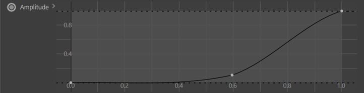
Amplitude
This spline control enables you to map the amplitude values returned from the FFT. You can think of it as acting like an audio filter. For example, this spline would ignore the effect of any low volume sound:
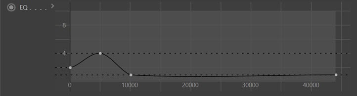
EQ
This is the same as the 'Amplitude' spline but for frequencies rather than amplitude. This spline would boost the effect of bass frequencies and ignore any higher ones: