OpenVDB Mesher
This is an implementation of the OpenVDB Mesher for X-Particles. For information about OpenVDB in general, please refer to its reference documentation pages.
For information about using this object, see 'Using the OpenVDB mesher' below.
Interface
The object's interface includes these sections:
For the buttons at the bottom of the interface, please see the 'Common interface elements' page.
Parameters
General quicktab

Below the General section there are several other sets of options. Which ones you will see depends on the setting in the 'Mode' parameter:
General section
These are general options applying to the mesher.
Mode
The mesher can operate in three different modes. These are as follows:
Mesh
This generates a polygonal mesh from the object(s) in the 'Sources' list. The resulting mesh depends on the options chosen for the source object - see the 'Mesh Mode' parameter for more details.
Spheres
In this mode, instead of creating a surface, the mesher will derive a voxel grid - which will not be displayed - from the object and then fills that with spheres. The parameters in this section allow you to control the sphere generation. As with the 'Mesh' option, the result depends on the source object options.
When you select this mode, another set or parameters becomes available, as described below.
ExplosiaFX
This mode generates an OpenVDB volume. You can render this with an Explosia FX object. Additional controls become available when this option is selected.
This mode was named 'Fog' in previous versions of X-Particles but the functionality has not changed.
Render Only
If this switch is checked, no mesh will be visible in the viewport and will only be seen when the scene is rendered to the viewport or picture viewer.
Link Voxel Size
If this switch is checked, the 'Voxel Size (Render)' parameter is not available, and will use the value from 'Voxel Size (Editor)'.
Voxel Size (Editor)
The voxel size when the mesher is shown in the viewport during scene editing. Generally speaking, this should be kept as large as possible for maximum speed in the viewport. As the voxel size is lowered the resolution of the mesh increases and any animation in the viewport will be slower.
Voxel Size (Render)
The voxel size when the mesh is rendered. This can be made lower than the voxel size in the editor for higher resolution and better results.
This parameter is not available if 'Link Voxel Size' is checked.
See the discussion below concerning voxel size and scale factor when selecting values for these options.
Half Width
Much of the time, you can leave this alone. It controls the width of the 'narrow band' of voxels included in the surface (see the discussion below). Reducing it can reduce the number of polygons generated and make the mesh appear a little sharper, but if you make it too small, you may start to see artefacts and holes appearing in the mesh.
Internally, the 'Voxel Size' parameter is multiplied by the 'Half Width' value and the result acts as a background or default value for the active voxels.
Point Options section
These settings are only effective if the 'Mesh Mode' for a polygon object is set to 'Points' or if the source object is a spline, a null object, or an X-Particles emitter. They have no effect on any objects if the object's 'Mesh Mode' is set to 'Surface'.
Point Radius
This controls the size of the spheres generated around each point or particle.
Min Point Radius, Max Point Radius
These are the limits on the size of the virtual sphere generated around each particle by the mesher (see the discussion below for full details). If the sphere size is outside these limits, it will not be included in the mesh. For the most part you can leave the default values as they are, but if you need to exclude very small or very large particles, you can alter these limits.
Mesh Options section
These are options used to control the nature of the generated mesh. They are only visible when 'Mode' is set to 'Mesh'.
Fill Interior Voxels
Checking this switch will fill all the voxels inside the surface of the generated object. This is mainly intended for use when meshing volumes.
Exterior Band Width, Interior Band Width
The interior and exterior band widths control how many voxels to fill inside and outside the volume respectively. It is recommended that you do not change these settings from the defaults unless you know exactly what you are doing. For example, increasing the exterior band width excessively will try to fill too many voxels with fog data than Cinema 4D can handle and it may appear to freeze.
ISO Value
This setting is only used when 'Mode' is set to 'Mesh'. It is the value in the VDB voxels which is considered to be on the surface of the mesh.
Mesh Adaptivity
This parameter is only available if 'Mode' is set to 'Mesh'. By increasing it you can reduce the number of polygons in the mesh but the mesh may look less rounded and not as attractive.
Relax Distorted Triangles
Checking this switch will relax any triangles that might be distorted due to mesh adaptivity. Note that this only has an effect if the 'Mesh Adaptivity' parameter is greater than 0.0.
Sphere Options section
These options are only used (and are only visible) when 'Mode' is set to 'Spheres'.
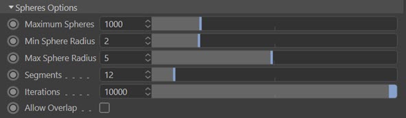
In this mode, instead of creating a surface, the mesher will derive a voxel grid - which will not be displayed - from the object and then fills that with spheres. The parameters in this section allow you to control the sphere generation.
Max. Number of Spheres
This is the maximum number of spheres that will be created, even if there is space to include more.
Min. Sphere Radius, Max. Sphere Radius
The size limits of the spheres. If they are both the same the spheres will be of uniform size.
Segments
The segment count for the generated spheres.
Iterations
This is the number of points in the volume the mesher will look at to place a sphere. The higher this value, the greater the chance of being able to place a sphere, but the mesher will take longer to complete the result.
Allow Overlap
If this switch is checked, the spheres will be allowed to overlap. This produces a cleaner fit of the spheres, but the spheres may (will) overlap one another.
ExplosiaFX Options section
These options are only used (and are only visible) when 'Mode' is set to 'ExplosiaFX'.
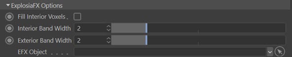
Fill Interior Voxels, Interior Band Width, Exterior Band Width
These are the same options as seen in the 'Mesh Options' section.
EFX Object
Drag an Explosia FX solver into this field. The solver will be used to generate the fog from its smoke channel.
Threading Options section
Grain Size
If set to higher than zero, the mesher is threaded. In practice the value in this setting makes little or no difference to the mesher speed in the current version.
Sources
This is a list of source objects the mesher will use. These objects could be (but are not limited to):
- an editable polygon object
- a polygon primitive object (Cube, Cone, etc.)
- an editable spline
- a spline primitive
- an X-Particles Trail object
- an X-Particles emitter
- a Mograph Cloner
- a Cinema 4D Null object
Multiple source objects can be used simultaneously. You can prevent any object from being meshed by unchecking the switch next to each object in the list.
Drag the objects you want to use into this list. When you select an object in the list, additional controls are presented. For a polygon object the basic controls are these:

Mesh Mode
Note that for emitters this menu is not used and the mesher always treats such objects in 'Points' mode.
This drop-down menu enables you to choose the mode used when building the mesh. It has three options:
Surface
The mesher will generate a contiguous surface from the object's vertices.
Points
The mesher will generate small spheres around each vertex. See the additional controls for this option below.
Volume
The object is treated as a volume. See the additional controls for this option below.
If you select an EFX Object in the Sources list, this menu is automatically changed to 'Volume' and cannot be altered.
Mesh Object
The actual object in the 'Sources' list will be meshed if this is checked. Turn this off to avoid unwanted mesh when meshing a null object with a child object. If it is left on, and 'Mesh Mode' is set to 'Points', unwanted geometry will be produced at the position of the null object.
Mesh Object Hierarchy
Leave this checked to mesh child objects of the object in the 'Sources' list.
Mesh Object Cached Hierarchy
When meshing an object with a cached hierarchy, this switch must be checked. Such objects would include any generator object which produces its output from one or more child objects. The Mograph Cloner is a good example of this. If this switch is unchecked but 'Mesh Object Hierarchy' is checked, only the actual child object(s) of the Cloner will be meshed, and not the output of the Cloner.
Generally, you can leave this switch always checked, and there are no problems if the object does not have a cached output. But if you have an object with a cached output and you don't want to mesh the cache, uncheck this switch.
CSG Mode
This is the method used by the emitter to control how multiple meshes are joined. The options are:
Union
The meshes from each source object are joined together to form one mesh.
Intersection
The volume where the objects overlap is meshed.
Difference
The volume where the object do not overlap is meshed.
Generate Object ID
If this switch is checked, the mesher will automatically generate a live vertex map for the mesh derived from the selected source object. The map can then be used, for example, to colour that part of the mesh. This means that the parts of the mesh derived from different source objects can have different colours.
Important: if you are generating the vertex maps by checking this switch, the tags are not cached if you cache the scene. This is currently a limitation of the caching system. This means that the vertex maps will no longer be visible in the scene when you select one of the tags. To show the maps again, you will need to delete the Cache tag on the OVDB mesher. Simply emptying the cache from the Cache object is not sufficient.
By increasing the smoothing iterations, the different colours can be blended, allowing the mixing of colours from the different sources. As an example, in this animation the two source objects are a Cube and an X-Particles emitter. Both source objects have this switch checked, and the vertex map from the Cube is used to apply a blue material only to the cube, so that a second material (red) is applied to the particle mesh. The smoothing iterations are set to 64, giving a blend between red and blue where the different parts of the mesh overlap:
Object ID Map Smoothing Iterations
The number of smoothing iterations to use in the vertex map when 'Generate Object ID' is checked for a source object. The higher the value, the smoother the blend between different maps.
Options in Points mode
If you select 'Points' mode, additional controls are provided:
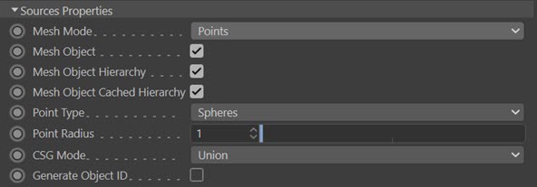
Point Type
There are two options in this menu:
Spheres
A sphere is generated around each point (or particle). In this case there is an additional option, 'Point Radius'.
Trails
These are NOT the same as the splines generated by the X-Particles Trail object! Each trail is a tapering mesh which forms behind the particle and whose length is dependent on the particle speed. If you use an object such as a Cube as a source for the mesher, the vertices of the object have no speed so only spheres are produced. This is the case even if the object is animated, since the vertex speed is zero in relation to the object.
Selecting this option shows more controls:
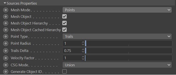
The options not already described are as follows:
Point Radius
This is only available when 'Mesh Mode' is set to 'Points'. It enables you to control the size of the generated sphere.
Trails Delta
When 'Mesh Mode' is set to 'Points' and 'Point Type' to 'Trails', the particle effectively gains a tapered tail behind it. This is built by the mesher as a series of spheres with decreasing radius. This setting controls how far apart the spheres are drawn. The farther they are apart, the less they are unioned together so increasing this value may result in the trail being drawn as a series of unconnected spheres.
You can increase this value as much as you like, but as you reduce it the number of computations required significantly increases, and if the value is too small, Cinema may appear as if it has frozen. To prevent this you cannot set the value to be less than 0.1.
Velocity Factor
When 'Mesh Mode' is set to 'Points' and 'Point Type' to 'Trails', the particle effectively gains a tapered tail behind it. The length of the tail depends on the particle speed, which leads to a problem: how do you obtain short trails without reducing particle speed (or long trails without increasing speed)?
This factor is simply a scale applied to the velocity. It does not change particle speed but the value passed to the mesher is altered by multiplying by this value. Reduce it for shorter trails and increase it for longer ones.
Options in Volume mode
If you select 'Volume' mode, more controls are provided:

The options not already described are as follows:
Value Threshold
This is used when meshing an ExplosiaFX object. It is the value in the EFX object data that is considered to be valid data; values below this are not considered valid. This can help to remove garbage data coming from the EFX object.
Link Voxel Size To Main Generator
If this switch is checked and the object is an Explosia FX object the voxel size will be set to the same as the voxel size in the Explosia FX object.
Voxel Size
This setting is only available if 'Link Voxel Size To Main Generator' is unchecked. Then you can set the voxel size independently of the source object.
Field
This drop-down menu enables you to select which Explosia data field to use for the meshing. The three options are Smoke, Fuel and Heat.
Info section
Show Output Info
If this switch is checked, then information about the generated object will be displayed. What is shown depends on the 'Mode' setting:
| Mode | Displays |
| Mesh | Number of points and polygons in the generated mesh |
| Spheres | Number of spheres produced |
| Fog | Number of active voxels |
Filters quicktab

Filters are smoothing routines which can be applied to the mesh. You can apply as many filters as you like, but note that the order the filters are in may affect the final result.
These filters may have very significant effects on the mesh, altering both its size and shape. There is one filter in the list by default, a simple 'Median' filter. You can delete or disable this if you wish.
Use Filters
If this switch is unchecked, no filters are used even if there are some in the list.
Filters
The list of filters. To add a filter, select one from the 'Add Filter' drop-down menu. To delete a filter, click its name in the list to select it, then hit the Delete or Backspace key. Alternatively, right-click the filter to show the context menu and click 'Remove' or 'Remove All'.
To disable a filter temporarily, uncheck the switch to the right of its name; or, right-click it and from the context menu click 'Disable'.
Add Filter
Select the desired filter from this drop-down menu.
Editing a filter
Some, but not all, filters have a value that can be changed. Click the filter to select it and a value field appears:

You can then alter the values. Not all value are available for all filters. Generally, it is best to experiment with them to get an idea of how they affect the final result.
Tags quicktab
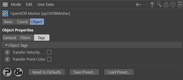
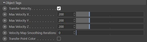
Transfer Velocity
If you check this switch, further options become available:
When the switch is checked, three Vertex Map tags and one combined Vertex Color tag are created on the OpenVDB Mesher object (the Vertex Color Tag is only created in Cinema 4D R18 and higher). These tags contain colour information for each vertex in the object, derived from the vertex velocity. These can be used to render a velocity map, which can then be used in compositing to produce motion blur.
The four tags are:
- a Vertex Color tag which is a combined RGB colour, representing the overall velocity along the direction of travel (only in Cinema 4D R18 and higher)
- three Vertex Map tags, which represent the maximum velocity value to compare the particle velocity to, in order to generate the velocity maps. For example, if the particle velocity is 150 units, then if the maximum velocity along a given axis is 200 units, this would generate a map with a weight of 75%
If you uncheck this switch again, the four tags are automatically deleted (you may need to click away from the OpenVDB mesher object to see this).
The options are:
Max VelocityX/Y/Z
This is the velocity which sets the relevant colour component to maximum (that is, the default setting of 200 units gives 100% of that colour component)
Velocity Map Smoothing Iterations
The velocity map can be smoothed to a greater extent by increasing this value.
Transfer Point Colour
Note: applies to, and is only available in, Cinema 4D R18 and higher (earlier versions do not have Vertex Color tags).
If you check this switch, this option becomes available:
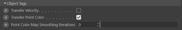
When the switch is checked, a Vertex Color tag is generated on the mesher which contains the colour from the particles. This can be used in a Vertex Map shader to render the mesh with the particle colours.
Note that as well as obtaining colours from particles, if a polygonal source object for the mesher already has a Vertex Color tag of its own, the mesher will transfer those colours to a Vertex Color tag on the mesher.
Point Color Map Smoothing Iterations
The color map can be smoothed to a greater extent by increasing this value.
Using the OpenVDB mesher
The OpenVDB mesher is extremely powerful and the main advantage over the inbuilt X-Particles Skinner is its speed. Typically it will mesh an object like this in under a second:

This was created by taking the vertices of an object which had 147,730 vertices and meshing it in the OpenVDB mesher. This shows the speed that this mesher can achieve.
How the mesher works
The mesher is supplied with three items of data for each particle (or vertex, if the source object is a polygon object or spline). These are the particle position, its radius, and its velocity. For polygon or spline objects, the radius is arbitrarily set to 1 and the velocity to zero, but for particles, the actual values from the particle are used.
With this data, OpenVDB constructs a three-dimensional grid to enclose all the points; each cell in this grid is a voxel. Voxel size can be changed with 'Voxel Size' setting.
Each voxel can be outside the surface to be generated, or inside it, or actually on or near the surface itself. The band of voxels at the surface, which are the 'active' voxels, is a narrow one and its width can be altered by changing the 'Half Width' setting. (This is why, if you read the OpenVDB documentation, this data is referred to as a 'narrow-band level set'.) All other voxels are considered 'inactive' and play no part in forming the surface.
The mesher then constructs a virtual sphere around each particle. The size of this sphere is the particle radius (or 1 if the object is not an emitter). If the spheres overlap they will be unioned, much as two sphere objects might be joined by a Cinema 4D Boolean object. If the sphere is smaller than the 'Min Radius' setting or larger than the 'Max. Radius' setting, it will not be included in the mesh.
Finally, if there are voxels within this sphere that are part of the narrow band, the sphere will be meshed, and the size of the generated polygons will depend on the voxel size.
Effect of changing settings
Knowing how the mesher works, we can predict what the effect of changing settings will be.
Changing the Voxel Size
if we reduce the voxel size, two things will happen. The generated polygons will be smaller and there will be more of them, so reducing voxel size will increase the mesh resolution; increasing it will reduce the resolution. For obvious reasons high-resolution meshes will take longer to generate than low-resolution ones.
The other effect is that the spheres surrounding individual particles may appear to increase in size. What is happening is that since there are more voxels the chance that a voxel falls within the narrow band is increased and more mesh is generated - up to a point. If the voxel size continues to decrease there may be no further visible change though the mesh resolution will continue to increase.
Conversely, if the voxel size is increased the number of voxels in the narrow band falls and the generated mesh will appear to reduce; if the voxel size is too large, there may be no mesh generated at all.
This video shows what happens when a cluster of particles are meshed and the voxel size is reduced from 4 to 2:
You can see that as the voxel size is reduced the mesh becomes smoother, individual blobs are better defined, and some particles which were not meshed at first begin to be meshed as well.
Changing the Half Width
Most of the time you can leave this unchanged. It alters the width of the narrow band of active (surface) voxels so if it is lowered you may see a slightly better definition to the mesh - though it is usually marginal at best. If you make it too small, some voxels which should be in the narrow band are omitted and you will start to see holes and artefacts in the mesh. In this video the half width value is reduced from 1 to 0.05. There are no visible changes until the value reaches about 0.32, when artefacts start to appear, and as the value is reduced still further, holes appear in the mesh:
In summary
The voxel size and/or radius scale you choose will have significant effects on the mesh. In general, for meshing an object with many vertices and great detail, such as the dragon used above, you would choose a small voxel size. But for cumulus clouds you would want the large, blobby appearance you would get with a large voxel size and particle radius. In the end it is a matter of artistic judgement.