FLIP/APIC Fluid Object
The Domain object is a FLIP (Fluid Implicit Particle) and APIC (Affine Particle-in-Cell) solver for the simulation of fluids.
Note that this object is now used only as a solver for fluid simulation. It is no longer used for smoke and fire simulation. For new scenes ExplosiaFX should be used instead.
For details of how to use the FLIP/APIC solver see the main Volume Rendering page.
Note that this is quite different from the SPH fluids and FluidFX objects also present in X-Particles.
Interface
The object's interface has several tabs and each tab is shown in its own section below.
For the buttons at the bottom of the interface and the 'Groups Affected' tab, please see the 'Common interface elements' page.
Object tab
Domain quicktab

These are general settings for the solver.
Voxel
This is the voxel size within the boundaries of the solver. The solver volume is divided into cubes of this size. Smaller values result in more accurate simulations but are slower to playback and render.
Note that if the voxel size is markedly different than the particle radius there may be insufficient particles per voxel. Ideally the voxel size should be 3-4 times the particle radius.
Size
The size of the solver, represented by a blue box in the editor. Particles will not escape from this box but will collide with its walls.
Type
You can select the solver type from this menu. The default is APIC and the alternative is FLIP. In general APIC produces a livelier, more detailed simulation, ideal for splashes. FLIP produces a quieter, smoother result.
Weak Spring
This is a weak force between the particles that push them apart to give better particle distributions during simulation. FLIP can lose volume over time and enabling this switch helps to combat that. Note that this does add some small overhead, turning it off will save some memory and computation time.
Strength
Only available if 'Weak Spring' is enabled. This value represents how strongly the particles are pushed apart by the weak springs.
Vorticity
When solving simulations energy and swirling motion can be lost due to inaccuracy and interpolation. Vorticity calculates this swirling motion and boosts it, enabling you to put back or boost this motion. This can be used to give more turbulent motion, especially useful for simulations that will have turbulent motion. Adding a Turbulence modifier can also help to inject additional movement to have larger or smaller motion. The vorticity in the Domain object is at the grid resolution.
Note that values higher than 100% are possible.
Viscosity
This setting changes the viscosity of a fluid. With higher values the particles stick together more strongly, giving a thicker, more treacly fluid.
Again, you can enter values higher than 100% if desired.
Surface Tension
Surface tension is defined as "the tendency of liquid surfaces to shrink into the minimum surface area possible" (source: Wikipedia). Increasing this value will make the liquid particles form a more coherent body. For example in these images with zero surface tension on the left and at 1000% on the right:

Liquid Level
This setting defines the liquid surface. As mentioned above, the voxel size is ideally three times the particle radius. If that is that case, this is a liquid level of 100%.
Reducing this value will effectively force the virtual liquid 'surface' closer to the particles and the result is a thinner, more splashy liquid. This is useful for small-scale simulations such as glasses of fluid, but not for oceans. Note that it is not possible to reduce this value below 50% as then the voxels cannot be reliably sampled.
Increasing this value forces the liquid to cover more voxels which is then more suitable for large-scale simulations such as oceans.
Sticky Objects
When liquid collides with an object there is usually some degree of stickiness, in that the fluid does not run off with no reduction in speed. If this switch is enabled, that effect can be reproduced in the solver.
Distance
Particles must be within this distance of the surface in order to show stickiness. If it is too low, particles may not appear to be sticking at all, but if it is too high, they may seem to stick some way away from the actual surface.
Bounce and Variation
This setting enables some bounce to occur when the particles stick. Variation between particles can be added with the 'Variation' setting.
Friction and Variation
This is the amount of stickiness. If you set it to zero, there is no stickiness at all but if set to 100% particles may remain permanently stuck. Variation between particles can be added with the 'Variation' setting.
Walls section
+X, -X, +Y, -Y, +Z, -Z
By default the solver has 6 walls, along the 6 orthographic axes (X+, X-, etc.). You can turn off any or all of these walls by unchecking the relevant switch. This is not just a cosmetic effect: particles will not rebound from disabled walls and will escape the solver. Once outside the solver they will not take part in the simulation.
Inflow
If an emitter is outside the domain, then if this switch is checked particles can flow into the domain but once inside cannot flow out again.
Solver quicktab

Retiming
As in the emitter, this value can be used to slowdown or speed up the simulation.
Simulation section
Accuracy
The FLIP/APIC domain is an iterative solver, refining the calculations each iteration. More iterations result in a more accurate simulation but will take longer to complete. The accuracy setting determines how close to 'exact' the solution is; the higher it is the more likely it is to reach the maximum number of iterations.
Iterations
The maximum number of iterations allowed, for very fast velocity changes (explosions) this may need to be higher if you notice artefacts (the 'Accuracy' setting may also have to be increased). Each iteration takes the particle velocities closer to being divergent free.
FLIP
This is only available when 'Type' is set to 'FLIP'. It is the ratio of the relative contributions of a direct voxel solution and particle flow to the final result. Blending the two helps to keep down noise from pure particle advection whilst keeping the fluid motion lively.
The lower the value the less is the contribution from particle flow and the slower and more viscous the liquid will appear.
CFL
The Courant-Friedrichs-Lewy number is important in controlling the accuracy and stability of the simulation. In this object the 'CFL' value is a percentage of the voxel size. If a simulation appears unstable (e.g. too lively or you see an exploding simulation) try reducing this value and/or increasing the 'Min Substeps' or 'Max Substeps' values. Both measures will, however, take longer to solve.
You don't need to understand the following technical explanation, but it will be of interest to some.
At the start of each frame the maximum speed of the particles and any colliders is used to calculate how small the substep time should be, so that the fastest moving particle doesn't move more than a percentage of the size of one voxel. This percentage value is set by the 'CFL' parameter.
This is fine provided that during those substeps the maximum speed doesn't change much, but with moving colliders and pressure against them it can jump the maximum speed significantly. Ideally you would then add more substeps to resolve this and keep the speed inside one voxel's size. This helps to damp down any rather over-excited voxels to keep stability, but as with any sort of damping, it comes with a price of losing a certain amount of motion.
Min Substeps, Max Substeps
The solving will only be accurate if particles don't move beyond a single voxel. The motion is broken into small times (substeps). These settings control the minimum and maximum number of time steps that will be used. Higher values, meaning more substeps, will slow the simulation but make it more accurate. For very fast moving fluids they may need to be higher if you notice incorrect simulations or artefacts.
Resampling
Checking this switch will make these parameters available:

If checked, the solver will examine voxels and either create new particles if there are insufficient particles in the voxel or delete particles where there are too many. The upper and lower limits on particle numbers are given in the 'Min' and 'Max' settings.
In most cases this can be left unchecked as it will slow the simulation down.
Min, Max
Click the little arrow next to 'Resampling' to see these parameters. They represent the limits on particle numbers per voxel if 'Resampling' is checked.
Obstacles section
Solid Objects
Checking this switch will use the voxels inside a hollow collision object, so if you see particles entering a collision object, check this switch.
If there are animated obstacles (collision objects) in the scene, you may sometimes see exploding simulations. If this happens, check this switch, which will correct the problem but result in longer simulation times.
Accurate Collisions
The simulation takes place in substeps (see 'CFL' above for more details). If this switch is checked, collisions are updated per substep, which is much slower but results in more accurate collisions per frame.
Object Inner Width, Object Outer Width
The inner and outer widths control how many voxels to fill inside and outside the volume respectively. If the band width is too small, liquids may enter collision objects, but smaller widths are quicker to calculate. A larger band width helps to avoid this sort of leakage, but if it is too large it may slow the simulation very markedly.
Adaptive section
Enable
The amount of memory required and time to calculate depends on the number of voxels used. Enabling this option will limit the voxels calculated to be only around those that contain any liquid particles. This helps to reduce memory use and speed up calculation when only a small part of the domain has any particles.
Note: if adaptive bounds are enabled motion blur in the domain will NOT work as the domain size changes with time.
Threshold
This setting determines the level below which there is considered to be no (zero) information in a voxel.
Expand
This setting expands the adaptive bounds by this number of voxels to allow the smoke/velocity within to flow into more of the domain. For fast moving simulations (such as explosions) this may need to be higher or adaptive not used as the fluid may flow out of the bounded volume.
Emitters tab
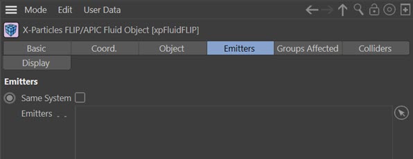
Normally, any emitter within the bounds of the domain will be affected by the FLIP/APIC solver. To exclude specific emitters, drag them into this list, where they will automatically be shown with a blue dash icon like so:
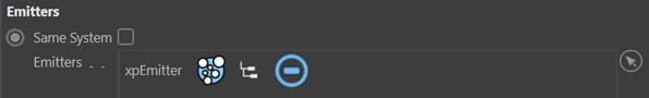
To re-enable the emitter to work with the solver, click the blue dash icon to turn it to a yellow tick.
Same System
If this switch is checked, only emitters in the same System object hierarchy as the domain object will be affected by it. If it is unchecked any emitters may be affected by the domain (if they are within its bounds, of course).
Emitters
The list of emitters.
Colliders tab
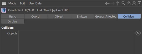
Any object inside the domain with a collider tag will act as a collider. If you want to temporarily prevent an object being used as a collider, drag it into this list, where it will automatically be shown with a blue dash icon like so:
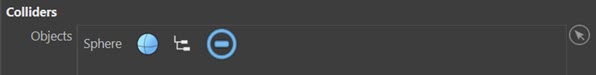
Other colliders will not be affected. To re-enable the object, click the blue dash icon to turn it to a yellow tick.
Objects
The list of objects you want to control.
Display tab
This tab controls the solver display in the editor.

Grid
This the solver display itself. The drop-down has four options:
None
The solver is not displayed in the editor.
Voxels
A 3D grid is shown with each grid cell corresponding to one voxel.
Back
A 2D grid displayed on whichever wall faces the camera (so it will change as the view is rotated).
Base
A 2D grid which is always displayed on the base of the solver.
Adaptive Bounds
If this switch is checked the domain object will display the interior bounds of the domain as they change during the simulation. This can help to see what is calculating and to fine tune the 'Threshold' and 'Expand' settings so you can see if the adaptive bounds are far enough away from where your smoke/fire is located. The reason for this is that the simulation may not look as good if the bounds are very close to the simulation.
Colliders
Collider objects (more properly 'obstacles' in the domain) will probably enclose many voxels completely, many not at all, and some only partially. Where the particles in a simulation hit the obstacle, you may see some leak through the obstacle geometry. These can occur where voxels are only partially enclosed by the mesh.
When checked, this switch will show solid red voxels (i.e. those enclosed by the collider object). If you see leaking particles, it can help decide where leaks might be occurring.
Velocity
If checked, the velocity (speed and direction) of the simulation are shown as coloured lines in the solver. The colours are taken from the 'Speed' colour and alpha gradients.
Note that if you cache the emitter(s) used in the scene, the velocity display is not possible since the voxels are not cached and you only have particle data.
Speed Color, Speed Alpha
Gradients used to control the display when 'Velocity' is checked.
Auto Range
When this switch is unchecked, the colour and alpha gradients for the speed are mapped to the 'Speed Min' and 'Speed Max' values. Depending on the simulation and the specified, you may see no or very faint velocities; if this happens, either adjust the speed range or check this switch.
If it is checked the domain will calculate the minimum and maximum speeds and use those.
Speed Min, Speed Max
These are the minimum and maximum speed values to use to map to the colour and alpha gradients, if 'Auto Range' is unchecked.