Emitter Display tab: Modifier Fields quicktab
This quicktab enables you to display the vectors generated by motion modifiers. Previously these could only be inferred from the effect on particle movement, but with this display option you can see the direction imparted to the particle and the effect on particle speed.
Here is an example display of the vectors from a Rotator modifier:

Note that only a subset of modifiers produce a vector display. Some cannot do so, because of the way they work. Those which do produce a display are as follows:
- Attractor
- Cover/Target (but only if the particle speed changes, e.g. you set 'Speed Mode' to 'Set Time to Reach Target')
- Explode (only if 'Set Speed at Start Only' is unchecked)
- Follow Surface
- Gaseous
- Gravity
- Rotator
- Sound Displacement (but only when the animation is playing and only when particle velocity changes)
- Speed
- SplineFlow
- Strange Attractors
- Turbulence
- Vortex (you must turn the 'Auto' switch off - see below - and set the min/max values manually)
- Wind
Other modifiers do not affect the velocity (that is, they only affect speed or direction). This means that with some modifiers certain conditions must be met to show a display, i.e. the velocity must be changed, which isn’t always the case.
Interface
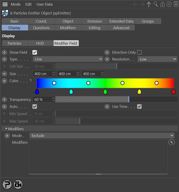
Show Field
Check this box to display the modifier field vectors.
Direction Only
If this switch is checked, the size of each displayed vector is identical. The speed effect is then only shown by the colour. If this is unchecked, the length of the displayed vector will be proportionate to the effect on the speed.
Note that this does not apply if 'Type' is set to 'Dot' since the size of the dots cannot be changed.
Type
This drop-down menu controls the vector display. The options are:
Dot
The vectors are shown as small dots. With this type, the vector direction cannot be seen but the effect on speed is denoted by the colour.
Line
The vectors are shown as thin lines.
Arrow
The vectors are shown as arrows. This is the default setting.
Resolution
For every point in 3D space there will be a vector value, but that is an infinite number of vectors and they cannot all be shown. You can alter the number of vectors shown with this drop-down menu. The options are:
Low, Medium, High
Preset values for the resolution. The default setting is 'Low' which is often good enough for most purposes.
Custom
With this option you can choose your own resolution by changing the 'Cell Size' parameter.
Cell Size
Use this parameter to determine the display resolution when 'Resolution' is set to 'Custom'.
Min, Max
These are the lower and upper limits of the display field respectively. Note that if the modifier has a falloff other than 'Infinite' then the vectors are only shown within the falloff area. Also, that if the falloff area is outside the field boundary, no vectors will be shown.
Color
The colours from this gradient are used to colour the vector display according to the effect the modifier would have on particle speed. As the speed change increases, the selected colour moves towards those from the right-hand end of the gradient.
Transparency
You can change the transparency of the displayed vectors with this parameter.
Auto
If this switch is checked, the range of possible speed changes on the particle is calculated automatically. This gives the best spread of colours from the gradient, since the minimum calculated speed change will use the colour from the left of the gradient and the maximum change uses the colour from the right of the gradient.
Very importantly, the speed does NOT mean the particle speed! It means the change in particle speed which occurs due to the vector in each voxel of the grid. If the vector does not change the speed, no vector will be displayed. The Direction modifier is a good example of this - it causes an obvious change in direction but not the speed, so no vector is displayed.
If you uncheck this switch, the range is determined manually from the 'Min Speed' and 'Max Speed' settings. For example, if 'Min Speed' is set to 50 and 'Max Speed' is set to 150, any vector causing a speed change of 50 or less will use the colour at the left-hand end of the gradient; any vector causing a speed change of 150 or more will use the colour at the right-hand end of the gradient.
Note that the speed change values may be surprisingly small. For example, with a Turbulence modifier, if you uncheck this switch and leave the 'Min Speed' and 'Max Speed' settings at their default values, you will see the vectors disappear. This is because the actual changes are very small - typically in the range 0 to 3.5. So you may need to change the min/max settings quite radically to see the vectors if 'Auto' is unchecked.
Very occasionally it may not be possible for the emitter to calculate the min/max values automatically and you will have to uncheck 'Auto' and set these values manually. The Vortex modifier is an example of this.
Use Time
In some cases, if a modifier parameter is animated the vectors may change from frame to frame. If this switch is checked, the vector display will be updated when the vectors change. Since the continual redrawing of the vectors can slow down playback, unchecking this switch will turn the display update off.
Min Speed, Max Speed
The minimum and maximum values to use if 'Auto' is unchecked.
Mode
You may not always want all modifiers to be included in the final display, or perhaps you need to specify one or more modifiers to use but not the others. You can do this by dragging modifiers into the 'Modifiers' list. If this drop-down menu is set to 'Exclude' none of the modifiers in the list will be included in the display.
If the drop-down is set to 'Include' only those modifiers in the list will be included in the display.
Modifiers
The list of modifiers to include in or exclude from the vector display. You can use this to specify exactly which modifier will be used to show the modifier vectors.