Data Mapping
Data Mapping in X-Particles
- Example
- What can you map a parameter to?
- Hints and tips for using data mapping successfully
- Reference
What is Data Mapping?
Put briefly, data mapping enables you to ‘map’ a parameter in a modifier or other object to an element of particle data or some other data value, such as the document time. This means you can adjust a parameter in accordance with the chosen data value.
Example
An example will make this clearer. Suppose you have an emitter which emits particles with a range of mass values – say a mass of 5 with a variation of +/- 4. You would like the particles with the greater mass to be more affected by a gravity modifier than the ones with less mass.
You can do this by mapping the gravity strength value in the modifier to the particle mass. To do this, go to the modifier's Mapping tab:
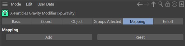
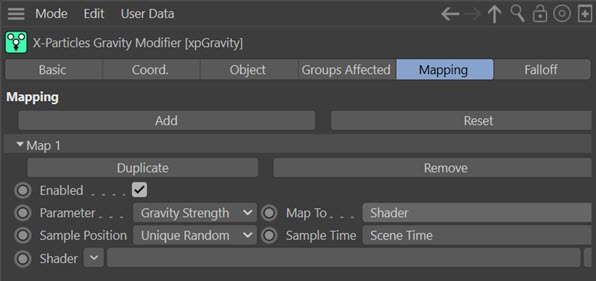
As you can see, the tab is empty by default. To add a map, click the large ‘Add’ button. The interface now looks like this:

The ‘Parameter’ drop-down menu is the modifier parameter you would like to map – in this case, the ‘Gravity Strength’ value. In fact in the Gravity modifier, that is the only parameter you can map, but some modifiers have many more than that. The actual parameters are, of course, unique to each modifier.
The ‘Data’ drop-down contains a list of data items you can map the gravity strength to; this list is the same for all modifiers. In this case, we want to map the gravity strength to the particle mass, so select ‘Mass’ from this list:

You also have two settings – 'Range Min.' and 'Range Max.'. These are the limits of the data values over which the spline control below will map the parameter to the data. Leave these alone for the moment.
Underneath you have a spline control which actually maps the strength to the mass. How it works is very simple: any particle with a data value (mass, in this case) which is the same as or lower than the ‘Range Min.’ setting is mapped to the left hand end of the spline. Since the minimum value is zero, this means that for any particle with a mass of zero (or less, but that’s not in fact possible for particle mass) will have a gravity strength applied to it of zero – that is, it won’t be affected by gravity.
For any particle with mass of 100 or above (since that is the value of the ‘Range Max.’ setting) will have the maximum gravity strength applied to it. In the Gravity modifier the default strength value is 981, so that will be applied to all particles with a mass of 100 or more.
Any particles with a mass between these two values will have a gravity strength applied depending on the value from the spline control. So if the mass happens to be 50, which is halfway between the minimum and maximum settings, the gravity strength will be multiplied by the spline value from 50% along the spline X-axis, which in this case will be about 0.5, giving a strength of 981 x 0.5 = 490 (approximately).
You can see that by altering the spline you can get very different effects. The default spline would mean that very light particles would have little or no gravity applied to them but maximum gravity would be applied to very heavy particles. Which is what we want – or is it?
Play the animation and look at what happens. You can see that gravity has very little effect on any of the particles, regardless of mass, which is not what we are expecting or what we want. This is because we haven’t set the range correctly. The particles have a mass range of 1 to 9 (5 +/- 4) but the mapped range is 0 to 100. So all the particles will take a spline value from near the left hand end of the spline, resulting in very low values. To correct this, set the 'Range Min.' to 1 and the 'Range Max.' to 9, then play the scene again. Now it looks much better.
Try altering the spline to give different effects. For example, note that particles with a mass of 1 will have zero gravity applied. We might want even those particles to be affected to some extent; to do that, drag the left hand spline point up a little so that the returned value is never zero. To make light particles affected but not heavy ones, simply mirror the spline so that the left hand point is at the top and the right hand point is zero.
You can map parameters to a range of different particle or other data values. The best way to find out what data mapping can do is to experiment – you will find that it opens up a large range of possibilities.
What can you map a parameter to?
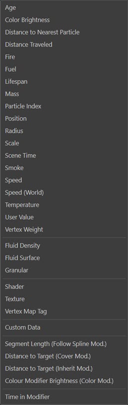
You can map a modifier parameter to a variety of data. The 'Map To' list contains the following entries:
Most of these are self-explanatory but some need a little more information. These include:
- Mapping to a position
- Mapping to fluid data
- Mapping to a shader
- Mapping to a texture tag
- Mapping to a vertex map tag
- Mapping to custom data
- Mapping to special modifier parameters
- Mapping to 'Time in Modifier'
- Mapping to 'Distance to Nearest Particle'
- Mapping to 'User Value'
For the other parameters, a brief explanation can be found in the Reference section of this page.
Mapping to a position
Selecting 'Position' from the 'Map To' list will change the map interface slightly to this:

With this you can map a parameter to the particle's position. The position can either be the particle's position in the 3D world or local to an object you specify. You can also test the direct distance to the world centre or the object, or restrict the distance to one axis - so you can map a parameter to the particle's Y-axis position, for example.
Space
This menu has two entries. If you choose 'World', the particle position is assessed in relation to the centre of the 3D world. If 'Object' is selected, the position is relative to the position of the object you drag into the 'Object' field.
Axis
The default option is 'All'. This simply measures the direct distance from the particle to the object or to the world centre. The other options let you specify the X, Y, or Z axis. If you select one of these, the distance along that axis to the world centre or object is used, and the other axes are ignored.
Object
Drag the object to use into this link field if you chose 'Object' from the 'Space' menu. An object in this field if 'World' was chosen is ignored.
Mapping to fluid data
These three data items allow you to map a variable to data which is available when using one of the X-Particles fluid objects.
Fluid Density
This maps the variable to the fluid density at the particle location. It requires a PBD Fluid object in the scene to return useful data. Without one, the returned density value is zero.
Fluid Surface
This option maps the variable to a value which measures how close to the surface of a fluid a particle is. Note that this is not an actual distance setting. Higher values indicate that the particle is close to the surface.
Typically, particles which are not near the surface return a very low value, often less than one. Conversely, those at the surface may return values of several thousands, depending on the settings in the Fluid FX object. You should bear this in mind when setting the range of values to map to.
The mapping requires a Fluid FX object in the scene to return useful data. Without one, the returned value is zero.
Granularity
This option maps the variable to the 'granularity' of a particle, which is directly related to the number of neighbouring particles. Granularity levels are therefore lower nearer the edges of the fluid since the number of neighbours is lower.
Typical granularity values returned are in the range zero to 30, but this varies depending on the Fluid FX object settings.
The mapping requires a Fluid FX object in the scene to return useful data. Without one, the returned value is zero.
Mapping to a shader
If you change the 'Map To' setting to 'Shader' the map interface changes slightly. Then you see this:
This lets you map any available parameter to a bitmap or Cinema 4D shader. What it does is sample the bitmap or shader at a point somewhere in 3D space and returns a value between 0 and 1, which is then multiplied with the parameter value. If the sample point is pure black it returns 0, and the parameter value will also be 0. Pure white returns 1, and the parameter value will not be changed. Any colour in between will reduce the value of the parameter depending on the colour brightness.
The following parameters are available.
Sample Position
This is a drop-down menu with three options:
Particle Position
With this option, the position in 3D space where the sample is taken depends on the particle position. Since that changes each frame (assuming the particle is moving!) the sample will change each time (again, assuming the colour in the shader/bitmap varies - a uniform single colour will always return the same value).
Unique Random
In this case each particle receives a unique random position in 3D space and uses that for the sampling. Clearly, this will always return the same value each time it is sampled (unless the shader is animated) so this can be used to set different values for different particles but then maintain that set value instead of changing it each time the sample is taken.
Emission UVs
When a particle is emitted from a polygon object using polygon centre, polygon area, object colour, texture or illumination modes, the UV coordinates of the emission point are calculated. In the emitter Extended Data tab, it is possible to specify that these coordinates are stored by the particle. If so, they can be retrieved and used to sample a shader or the texture in a texture tag.
To do this, you must:
- emit particles from a polygon object using one of the modes listed above
- turn on 'UV Emission Data' in the emitter Extended Data tab
- choose 'Emission UVs' from this drop-down menu
Then the sample will always be taken at the same UV coordinates. This has the greatest usefulness when you map to a texture (see below) rather than directly to a shader. This method when used with a shader will only cause the sample always to be taken at the same point, so will behave much like the 'Unique Random' option. But when sampling a texture the same point on the object will be sampled, resulting in different results if the texture is animated..
Sample Time
With an animated shader the time the sample is taken also affects the result. This parameter will have no effect with non-animated shaders so for those it can be left at any setting.
It is recommended that if you only want to see the effect of time on the shader sampling, you set the 'Sample Position' to 'Unique Random'. If you use 'Particle Position' instead, the sample result will always change if the particle has moved.
This is another drop-down menu with two options:
Scene Time
The current scene time is used when sampling. Clearly, the same result will be produced for each particle since the scene time is the same for all of them. See the highlighted note above regarding the 'Sample Position' setting.
Particle Age
The particle age is used instead. A different result will be produced for different particles if their ages are different. Those which have the same age will produce the same sample result (but see the highlighted note above regarding 'Sample Position').
Shader
Add any C4D shader or a bitmap into this link field.
Mapping to a Texture Tag
If you change 'Map To' to 'Texture' the interface appears like this:

This works in the same way as mapping to a shader (see above) but uses a texture tag from an object instead. It works in exactly the same way and the 'Particle Position' and 'Sample Time' parameters are the same.
Note: see in particular the discussion regarding 'Emission UVs' above. This has particular relevance when mapping to a texture tag.
The other settings are:
Channel
This is a drop-down menu which lets you choose which channel to sample from in the material. This can be one of these channels:
- Color
- Luminance
- Transparency
- Reflection
- Bump
- Alpha
- Displacement
- Diffusion
Note: if the channel does not contain a shader or bitmap, the standard or default colour of the channel is used, except for the the Bump, Alpha, or Displacement channels. If one of those channels is selected and the channel does not contain a shader, the generic colour of the Color channel is used instead (not the colour of any shader which might be in the Color channel, just the standard 'Color' setting).
The settings on the tag itself are not relevant. The selected channel does not have to be used in the material. As long as it is present in the material, it can be used for this purpose. (Unused channels can be accessed through the Cinema 4D material manager, but not via the attribute manager.)
Zero Point
By default this is set to zero and in this case the mapping will return a value of zero for black in the texture and 1 for white. However, you cannot return negative values, which you might want to do to slow down a particle in a Speed modifier, for example. By moving the zero point you can now do this. If you set this value to 50%, which corresponds to mid-gray in the texture, the mapping function will return values ranging from -0.5 for black to 0.5 for white. A value of 100% will return a range from -1.0 to 0.
Be aware that returning negative values is not always a good idea and may lead to strange or completely broken results in some cases. Use at your own risk!
Texture Tag
Drag the texture tag you want to use into this link field.
Mapping to a Vertex Map Tag
If you change 'Map To' to 'Vertex Map Tag' the interface appears like this:

In this case the parameter is mapped to a vertex map tag. This can be a tag from the object the particle was emitted from, or a tag from a completely unrelated object. The vertex weight is obtained from the tag and used to map the parameter. Note that the ranges are the limits of the vertex weights in the map.
The main choice here is which vertex to use for each particle. If you are emitting from the vertices of a point or polygon object and you check the switch 'Emission Vertex' in the emitter's extended data tab, the parameter is mapped to the weight of the vertex from which the particle was emitted. If you don't check that switch, or it is checked but you are not emitting from the vertices of a point or polygon object, a vertex is chosen based on the unique particle ID number. This will always be the same, and therefore the sampled vertex is always the same, for a given particle, but in most cases will not be the same as the vertex the particle was emitted from (if it was emitted from a vertex at all, of course).
Vertex Map Tag
Drag and drop the tag you want to use into this field.
Mapping to custom data
You can also map parameters to custom data items you have added to the particles. For details of how to add custom data, see the emitter's custom data page and for how to use custom data, please see the particle custom data page.
When you select 'Custom Data' from the 'Map To' menu, the interface looks like this:

You now need to specify the data type, which can be a Float, Integer, Time or Vector data item. Then you must provide the custom data ID value and/or the Name of the item. You can find a detailed explanation of these parameters in the emitter's custom data page.
Once that is done, you can set up the range and spline as with any other data item.
Data Type
You should be aware that the 'Data Type' parameter is very important. If the data item is of one type but you select a different type in this drop-down menu, the mapping may not work correctly and may not work at all.
If you specify in this menu that the data type is a Float and it's actually an Integer, that shouldn't matter and mapping will work correctly. If you specify that it is an Integer but it is actually a Float, the mapping routine will convert the Float to an Integer, which will lose some arithmetical precision. This may or may not matter; if the actual value of the data item is (for example) 100.5 and it is converted to 100, you're unlikely to see any problems. But if the actual value is 0.9 and the range values are set to be from 0 to 1, the conversion from Float to Integer will result in a value of zero - which is likely to have a major effect on the result.
Finally, Time and Vector data items must match the data type given when the data item was added. The mapping function will not convert to or from these data types, so a mismatch here will result in mapping having no effect.
Mapping to special modifier parameters
In many cases you will map a parameter to an inbuilt particle parameter such as radius, mass, etc. Some of the X-Particles modifiers and objects add their own data to the basic particle data, and it is possible to map parameters to that data, too. For example, if you select 'Distance to Target (Cover Mod.)' from the 'Map To' list, you can map a modifier parameter to the distance between a particle and the target point used by a Cover/Target modifier. You could use this to change a particle's speed by using a Speed modifier and mapping the 'Speed Value' parameter to the distance to the target.
When you map to such a data value, you need to ensure that the particle is being affected by the appropriate modifier. If it is not, no effect will be seen. The modifier you need is given in the name of the data value - e.g. 'Distance to Target (Inherit Mod.)' requires that the particle being mapped is influenced by an Inherit modifier.
Note that you will need to choose the ranges carefully. For example, the 'Distance to Target (Cover Mod.)' map might have a maximum range of several hundred screen units. The 'Color Modifier Brightness (Color Mod.)' map on the other hand will always return a value between 0 and 1, so the range you chose should be within those limits.
Mapping to 'Time in Modifier'
With some modifiers, you can map a parameter to the time spent in the field of effect of that modifier. This will be reset to zero if the particle leaves the modifier's field and enters that of another modifier of the same type.
This is a time variable so if you select this, the range settings will change to be of the time type.
Not all modifiers have this facility. If a modifier does not, this entry will not be present in the 'Map To' menu.
Mapping to 'Distance to Nearest Particle'
To use this option, you MUST enable 'Nearest Particle Data' in the emitter's Extended Data tab. Note that mapping will only occur between particles emitted from the same emitter, not between different emitters.
The selected parameter will then be mapped to the distance to the particle's nearest neighbouring particle. If the distance exceeds the 'Range Max.' setting, the value from the right-hand end of the spline will be used. If the distance is less than 'Range Min.' the value at the left-hand end of the spline will be used.
When using this parameter, consider the effect of the spline itself. In this screenshot, the 'Red Rate of Change' setting in a Color modifier is mapped to the distance to the nearest particle:

The maximum value is set at 30 screen units. This means that any particles whose nearest neighbour is more than 30 units away will show no change in the colour's red value at all (because the value returned from the spline will be zero). This is probably what you want to achieve in most cases. But what happens if the spline is flipped horizontally like so:

Now, the maximum rate of change in the red value is seen in particles whose nearest neighbour is more than 30 units away, and those whose nearest neighbour is closer will see a lowered rate of change. Since the screenshot above is the default spline used when a new data map is created, you may need to flip the spline to achieve the desired effect.
Mapping to 'User Value'
The emitter's extended data tab has a setting named 'User Value'. As its name implies, this is a setting which the user can set to any required value. It is possible to map parameters to this data value using this option. The advantage of this is that it is no longer necessary to assume that a particle data item such as mass is not being used, and to set such data to some arbitrary value for mapping purposes. If an arbitrary value is required, use this data item instead.
Hints and tips for using data mapping successfully
1. Set the range correctly
Always be sure to set the range correctly. This is absolutely critical. An incorrect range will not produce the results you expect, so if things don’t seem to be working check the range. As a general rule, you should set the Minimum value to be the lowest value you expect the data to reach, and the Maximum to be the highest expected value. With experience you can alter the ranges to suit the desired result, but be aware that you may not see exactly what you expect.
Note that not all data items have a range - for example, the particle lifespan is a fixed value, so a range is not applicable.
2. Not all modifier parameters can be mapped
Mappable values are those which have a continuously variable value, like the ‘Gravity Strength’ in the above example. These can be integers, floating-point numbers, or time values. However, on-off switches or drop-down menus cannot be mapped. In some cases, a value which looks as if it should be mappable is not. This is usually because the parameter is fixed for a particle as soon as it enters the modifier’s field of effect, so changing the parameter value after that happens will have no effect.
3. Not all modifiers have a mapping tab
If they don’t, it is because none of the parameters in that modifier can be mapped.
4. Mapped parameters cannot be increased in value
Whatever parameter is being mapped, note that the value cannot be increased above the value set in the modifier or other object. For example, if the ‘Gravity Strength’ value in a Gravity modifier is set at 500 units, the data mapping can only return a maximum gravity strength of 500 – it can never return a value or 501 or 600 or higher.
5. No negative values
The data mapping can never return negative values (unless the modifier setting itself was negative). That is, if the ‘Gravity Strength’ value in a Gravity modifier is set at 500 units, the data mapping can only return a value of 0 to 500; it cannot return a value of -200, for example. However, if the value in the modifier was set to -200, then the data mapping can return a value ranging from 0 to -200.
6. Time variables
These can be very confusing when mapped. Suppose a parameter in a modifier is a time when something should happen - to repeat an action every so many frames, for example. Now imagine that this value is set to 30 frames, and it is mapped to any data item with a spline like this (the Branch modifier is shown here with the 'Bend In' time parameter mapped to particle radius):

At the left hand end of the spline, when the radius is very small, the value returned by the spline is zero, so the time parameter value is mapped using that spline value, giving it a time of zero (effectively, this means the action will usually take place immediately). So with a low value from the spline, things happen sooner than they would be expected to. This can be really confusing, because instinctively you expect a lower value from the spline to make things happen less frequently - but in fact, they will happen more frequently. If you find this confusing, the answer is to reverse the spline so it has the maximum value at the left hand end; then larger values on the spline will result in the time parameter approaching its maximum.
7. Vector variables
A vector is slightly different to other variables because it has three components. When comparing vectors therefore, the magnitude of the variable is used. Note that what appear to be different vectors can have the same magnitude: for example, a vector of [1,0,0] will have the same magnitude as a vector of [0,1,0] or [0,0,1].You should be aware of this when mapping a parameter to a vector.
8. Not all mapped parameters will always have an effect
Suppose there is a parameter in a modifier which is only available to you under certain conditions - in other conditions the parameter may be greyed out or not be visible at all. Such parameters can still be mapped, but the mapping won't do anything because the parameter being mapped is not actually used. You should be aware of this if you map a parameter and it doesn't seem to do anything - always check to see that the parameter itself is actually used!
Reference
Add
Click this button to add a new map.
Reset
To remove all maps from the modifier, click this button. You will be asked to confirm that you want to do this.
Within each map, the following controls are available:
Duplicate
Click this button to duplicate the map. This can be very useful if you have set up a custom spline and want to use the same spline to map some other data item. Simply use this button to duplicate the map, then adjust the 'Map To' setting and range values accordingly.
Remove
Click this button to permanently remove the map.
Enabled
Uncheck this switch to disable the map. This is useful if you want to try out several different maps, because it makes it easy to set up the maps with differing parameters and then switch between them. Or you can try maps in combination and enable or disable maps to see the effect of each one.
Parameter
The parameter to be mapped. This drop-down list contains all the parameters of the modifier which can be mapped. A parameter which is not in this list cannot be mapped.
Map To
The data item to map the parameter to. The available items are:
| Data item | Data type | Range units |
|---|---|---|
| Age | Particle age. | Time |
| Color Brightness | Particle color brightness. | 0 - 100% |
| Distance to Nearest Particle | The distance to the particle which is nearest to this one. | Scene units |
| Distance Traveled | Total distance travelled by the particle. | Scene units |
| Fire | Particle fire value. | Floating-point number |
| Fuel | Particle fuel value. | Floating-point number |
| Lifespan | Particle lifespan. | Time |
| Mass | Particle mass. | Floating-point number |
| Particle Index | The unique index number of the particle. | 0 to the maximum number of particles |
| Position | The particle's position in the 3D world. | Vector |
| Radius | Particle radius. | Scene units |
| Scale | Particle scale. | Vector |
| Scene Time | Current time in the document. | Time |
| Smoke | Particle smoke value. | Floating-point number |
| Speed | Particle speed. | Scene units |
| Speed (World) | Speed of particles stuck to the object they were emitted from. Requires that 'World Speed' is enabled in the emitter Extended Data tab. | Scene units |
| Temperature | Particle temperature value. | Floating-point number |
| User Value | The 'User Value' found in the emitter's extended data tab (physical data). | Floating-point number |
| Vertex Weight | If the particle was emitted from a vertex of a polygon object, using a vertex map, the vertex weight of that vertex. | 0 - 100% |
| Fluid Density, Fluid Surface, Granular | Fluid data. See Mapping to fluid data above. | Floating-point numbers |
| Shader | A Cinema 4D shader or bitmap. | 0.0 to 1.0 |
| Texture | A Cinema 4D texture tag. | 0.0 to 1.0 |
| Custom Data | User-specified in the emitter. | Various |
| Segment Length (Follow Spline Mod.) | The length in scene units of the segment of the spline that the particle is currently following. For a single-segment spline, this is the same as the spline length. | Scene units |
| Distance to Target (Cover Mod.) | The distance the particle still has to travel to reach its target point on an object. | Scene units |
| Distance to Target (Inherit Mod.) | The distance between a particle and the other particle it will inherit parameters from. | Scene units |
| Color Modifier Brightness (Color Mod.) | The color brightness value from a Color modifier. The switch 'Store Color Brightness' in the modifier must be checked to use this data, | 0.0 to 1.0 |
| Time in Modifier | The time the particle has been in the modifier's field of effect. Not available for all modifiers. | Time |
Range Min., Range Max.
The ranges used to map the parameter to the data item. The units of the range will vary depending on the 'Map To' parameter; the units for each data type are shown in the above table.
Mapping
The spline used to map the parameter to the data item.