Tags: Cloth FX Tag
The Cloth Tag is the main controller of an object which is to be used as cloth. If the object does not have a Cloth Deformer as a child object, the tag should be attached directly to the object. If there is a deformer, the tag should be on that deformer rather than on the object itself.
Interface
The tag contains three tabs dealing with different aspects of the cloth:
Parameters
Cloth tab

For the buttons at the bottom of the interface, please see the 'Common interface elements' page.
Enabled
Lets you start the simulation at a specific frame. The cloth is still initialized on the start frame so it will not take on the shape of any deformations that occur from the start frame until this option is enabled. This option can also be used to stop the simulation.
Emitter
A link to the XP emitter. An appropriate emitter will automatically be created when you click on the “Create Cloth” command when either a Polygon Object is selected or a Cloth Deformer is selected. The “Create Cloth” command will also add a cloth tag and set this emitter for you if there is not a cloth tag already set.
Iterations
Sets the number of times the cloth simulation is run each time step. A higher number produces a more rigid cloth like sheet metal, while a lower number will produce a very soft flexible cloth simulation.
Second Level Constraints
This will add additional constraints to every point that is “2 points” away from the start point.
Third Level Constraints
This will add additional constraints to every point that is “3 points” away from the start point.
Keep Velocities
If this switch is unchecked (the default setting) the particle velocity will be altered by the cloth modifier to improve the cloth behaviour when the particles move. If it is checked, the particle velocity is unaltered, so they have the velocity they would have had in the absence of the cloth effect. This can produce a different appearance, which may or may not be desirable.
Dampen
This setting (which is not available if 'Keep Velocities' is checked) will dampen the forces applied to the particles by the cloth modifier. You can use it to smooth out the particle movement but at high values you will see little or no movement at all.
Structure & Strength
Create constraints to the left, right, top and below a given point on the mesh.
Strength set how strong the constraint is. The lower the value the less effect this constraint has.
Shear & Strength
Create constraints from the top-left to the bottom-right and the top-right to the bottom-left on each individual quad.
Strength sets how strong the constraint is. The lower the value the less effect this constraint has.
Bend & Strength
Create constraints 2 points away upwards, below, to the left and right of a point.
Strength sets how strong the constraint is. The lower the value the less effect this constraint has.
Plasticity
Cloth is normally springy when pinned and when something collides with it, it tends to return to its original shape. If this switch is checked, the cloth becomes plastic in nature and once deformed it remains that way.
In this scene, plasticity is disabled:
This is the same scene but with plasticity enabled:
Start
This is a measure of how much force must be applied to cause the plasticity effect. If you set this too high, you will not see any plasticity and either it must be reduced or the force increased (for example by increasing the colliding object or particle's speed) to see the effect. If it is too low, the plasticity effect may be excessive and you can correct that by increasing this value or reducing the force.
As an example, in the above scene a value of more than 1.3 completely removed the effect.
Limit
This is the maximum plastic effect that will be generated. It MUST be higher than the 'Start' value to see any effect. The greater the difference between 'Start' and 'Limit' the greater the effect will be.
Simulate
All Immediately
Simulates all cloth points immediately
All on Collision
Simulates all cloth points after any collision object has hit them
Collided Points Only
Simulates only the cloth points that have been hit by an object
The following will also appear if the tag is on a Cloth Deformer
Falloff
Simulate, and continue to simulate, any points touched by the falloff
Falloff Inside Only
Only simulate any points inside the falloff.
Falloff Collision
Simulate, and continue to simulate, any points that are inside a falloff and have been hit by a colliding object.
Falloff Collision inside only
Only simulate any points that are inside a falloff and have been hit by a colliding object.
Quad Bend Constraint
This option will allow you to define how rigid the quad should be on the cloth. This is most noticeable on low polygon objects, but can be used on higher density cloth as well for a specific simulation look and feel.
Set Initial State
Note: do not use the 'Set State' button in the emitter when using cloth as the cloth system cannot then function.
This option only becomes active when the Cloth Tag is on an editable polygon object. When you first add a Cloth Tag to a polygon object the tag makes a copy of the current state of the polygon object’s points. If you want to change the cloth then you can either (a) make the change to the cloth and then press the 'Set Initial State' button, or (b) delete the Cloth Tag, make your change and then re-add a new Cloth Tag. If you choose option (a) then make sure you do not animate the scene when you make the changes, otherwise doing so will cause the Cloth Tag to overwrite the change at frame 0. This option can also be used to set a starting frame for your cloth. You could animate the cloth to until it reaches your desired look and then press the 'Set Initial State' button.
Clear Initial State
This will clear the initial state.
Additionally if you delete the Cloth Tag the initial state will also then be cleared and the object returned to its original state.
Tearing tab

Tearing
Enables the tearing on the cloth.
Tearing Strength
Cloth is torn when its constraint goes past a breaking distance. The default breaking distance is set to the distance between the two points at the start of the animation. Adjusting this value will increase the breaking distance by multiplying it against the default distance. You can also go negative if you wish the constraints to break immediately.
The vertex Map is used to define what areas should be torn. The map is used in conjunction with Block Tearing to define how the cloth should be broken apart.
This example shows the effect that can be achieved:
This is the vertex map used to indicate where the cloth should tear:

Stress Break Count
Tearing occurs when a constraint between particles is stressed and broken. If you increase this value, the number of times a constraint must be stressed before it breaks is increased. The result is that tearing first occurs in the most highly-stressed areas of the cloth.
Cracking
Enabling this switch will cause a crack to appear in the cloth and tearing will expand from that point.
Weakness
This is only available if 'Cracking' has been enabled. It represents the strength of the constraints along the cracking edge. The higher it is the more likely the crack will expand. If it is set to zero you may not see any tearing, depending on the other parameters in the tag.
Tearing Method
There are two different tearing methods that produce slightly different results depending on the look you are after.
Simple
When a constraint for a point is broken it will break away the point so that all the polygon that shared that point are now all broken off. This method produces results where the cloth will tear itself into multiple pieces when stretched beyond its breaking limits. It is good for destroying the cloth completely.
Advanced
When a constraint for a point is broken it will look at keeping edges connected along the cloth.
Where as simple will just break away all the polygons the advanced method will keep edges
connected and will break away in straight lines along the breaking direction.
This method is good for breaking apart the cloth internally to review weak spots and produce
interesting tearing simulations within a cloth structure itself, without it tearing apart into smaller
bits too quickly.
Use
Will use the vertex map, if there is one assigned, to restrict the tearing to specific areas of the cloth
Invert Map
Inverts the vertex map
Tear Map
The vertex map to use to define where the cloth should tear.
Block Tearing
When this option is enabled the painted areas on the tear map will be treated as if they are solid parts of the mesh and the boundaries between painted and non-painted areas are where the cloth should tear. If this option is disabled then it will do the opposite and define the painted parts as the weakest portion of the cloth and break them first.
Collided Points Only
Will only tear points that collide with an object that has a Cloth Collide Tag.
Wait For Collision
Will only start the tearing detection once a collision is detected.
Structure Horizontal
When enabled it will check the structure constraints that go horizontally across the surface to see if they should break. The lower the strength the weaker the constraint and the more likely it is to break.
Structure Vertical
When enabled it will check the structure constraints that go horizontally across the surface to see if they should break. The lower the strength the weaker the constraint and the more likely it is to break.
Break Percentage
When constraints are broken, they are ordered from those which are most likely to break to those which are least likely, based on the amount of stress on each constraint. By default all constraints will break if they are stressed enough and they exceed the main “Tearing Strength” set for the cloth.
By reducing this value you can limit the number of constraints that will break each time step. For example, setting it to 10% will mean that only the top 10% of the highest stressed constraints will actually break. 1% will break only the top 1% of the constraints.
Random Break
Along with the Break Percentage you can also randomly choose a percentage of these top constraints that you want to break. So if Break Percentage is set to 10% and Random Break is set to 50% then it will randomly choose 50% out of the top 10% of the constraints, and only break them.
Seed
The seed value for the random number generator used for 'Random Break'.
Percent
The percentage value used if 'Random Break' is enabled.
Break Poles
Some objects, such as a sphere, have more than 4 edges connected to a point. These are termed 'poles'. By enabling this option all the edges at these poles will be broken as soon as any of the edge constraints are broken. Otherwise, it may only break away one or two edges leaving the rest intact, and they may never break apart due to reduced stress on these locations.
Output Tear Map
If a map is applied to this link then anytime a point is torn it will apply paint to this vertex map.
Create
This button will create a vertex map on the Polygon Object and apply it to the Output Tear Map.
Draw Constraints
By using the Draw Constraints option only with each of the individual constraint types you can see what constraints are active and which ones will break, if you are using tearing.
If you have tearing enabled then any constraints that are going to break will be red. All other constraints will be green. If you pause your simulation then you can adjust any of the tearing options and see the effect on the surface and what parts will be breaking. This is particularly useful when adjusting the Break Percentage and Random Break sliders.
Groups
You can drag one or more particle groups into this list and only those groups will then tear.
Advanced tab
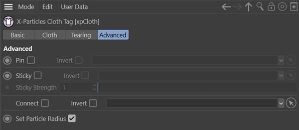
Pin
Pinning enables you to use a vertex map to indicate that some points should not be simulated at all. It excludes them from the simulation and currently they are locked to world space coordinates. The link field for a vertex map tag or point selection tag becomes available when this switch is checked.
This example shows a cloth object with the 'top' row of vertices pinned using a point selection tag. The tag interface looks like this:
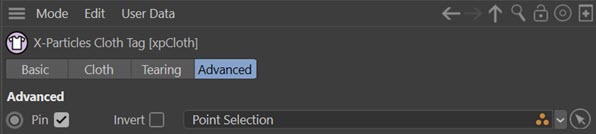
Resulting in this animation:
Invert
If checked, this switch inverts the pin map so only those vertices in the map take part in the simulation.
Sticky
The sticky options allow you to use a vertex map to indicate that some points are stuck and shouldn’t be simulated until forces pull them away from their stuck positions. To peel away the surface you should have a higher Tearing Strength set for your cloth so that it doesn’t immediately start tearing.
The link field for a vertex map tag or point selection tag becomes available when this switch is checked.
It needs enough force on the torn off parts of the cloth so that they can pull up the sticky parts of the cloth. Like peeling paint away from a surface. Be sure to leave some part of your cloth unstuck, i.e. not painted on the vertex map. Otherwise the entire cloth will be sticky and nothing will be evaluated. By leaving some parts unpainted they will be simulated and start pulling and un-sticking the other parts of the cloth.
In this example, the cloth object has this vertex map applied to it:

Note that in the tag the map is inverted ('Invert' is checked) meaning that the entire map is painted - and therefore sticky - apart from one corner. This is the sticky map, which is then added to the interface:
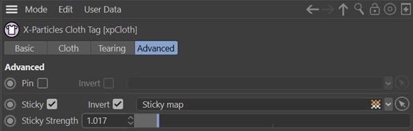
And gives the animation below. The peeling effect happens because the vertices in the unpainted corner (the map is inverted, remember) are moved by the modifier and then pull the rest of the cloth with them:
Note that in this case the cloth peels upwards due to the particles being moved by a gravity modifier pointing up instead of down.
You can also combine stickiness with tearing as in this example. Here, a second vertex map has been added to the 'Tear Map' link to indicate where the cloth will tear:
Invert
If checked, the sticky map is inverted, as in the above example.
Sticky Strength
How strong the sticky constraint is. Adjusting this, along with the vertex map, will define how sticky the surface is.
Connect
This option is used when the cloth collides with another object. In this example, the sphere has an X-Particles Collider tag attached, so the particles on the cloth object will collide with it. The results are what would be expected:
The Collider tag has an option to connect particles with the collider object when a collision occurs. If that is enabled, all particles which collide with the sphere will connect to like this:
But suppose we only want part of the cloth object to connect? That is what this option is for. We can create a point selection tag on the cloth object like so:

If we now enable the 'Connect' option in the cloth tag and drag the point selection tag into the link field, we see this:
Invert
If checked, the selection or vertex map is inverted.
Set Particle Radius
If checked, this option sets the size of the particles so that the Constraints object works for collisions with cloth and particles. Normally this should be left checked.